 Owen Trueblood
The design for the coarse positioning stage for Jack uses two voice coil motors and a quadrature signal from two Michelson interferometers to get the fine positioning stage (piezoelectric scanner) within about 100 nm of a region of interest. By having two positioning stages using different mechanisms for their motion I’m hoping to obtain a much larger scanning area than other DIY scanning probe microscopes have achieved in the past. Instead of about 10 square micrometers for a microscope with only piezoelectric positioning, Jack should be able to cover about 1 square centimeter. Whether it’s possible to use both stages at the same time to get atomic resolution over the full square centimeter is something I want to find out.
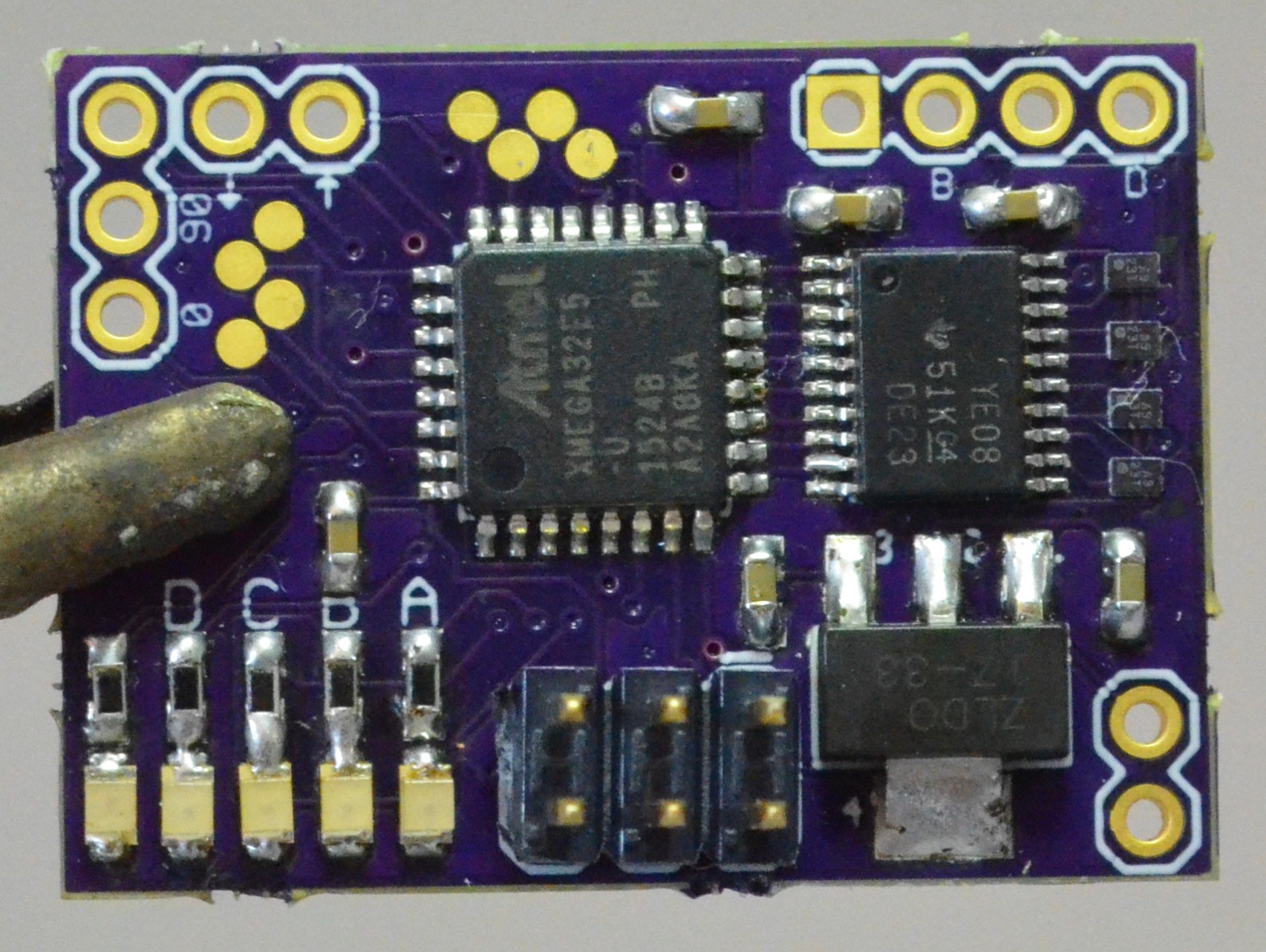
To drive the voice coil stage I’ve designed this small circuit board. It has at ATxmega32E5 as its brains. I chose an xmega because: 1) At 32 MHz it's plenty fast for this job. 2) It has a built-in quadrature decoder. 3) I’m a big fan of the AVR family but have never tried the xmegas.
The xmega talks to four LV8498CT voice coil motor driver chips. These are really neat ICs. They are designed for driving focus coils in cameras or phones with cameras. You give them 5 volts and instructions over I2C and they give your coils a precise amount of current up to 150 mA. I figure that they will be able to scan at rates up to a couple of kilohertz, which is good for experimentation but I’ll probably need to design my own coil driver so I can go faster in the final microscope and not have to wait a quarter of an hour per scan.
Assembling the board was a joy, but there was some fear before I started. If you look at the right side of the picture of the assembled board above you’ll see the four coil drivers. You might be confused and think, “how is that a whole driver IC? Those parts are smaller than the 0603 resistors and caps on the rest of the board!” The reason the drivers are so small is that they are in wafer-level packages. This means they are actually tiny slivers of silicon without the usual epoxy packaging (the picture doesn’t show it, but they sparkle beautifully in the right light). There are 6 miniscule solder balls on the bottom of each for the connections. I was not sure if OSH Park could even meet the specs for the package, let alone if I could solder them. But as it turns out you can just lay down some flux, forget the solder paste, position ICs with a needle, and go at them with a hot air gun. The little guys align themselves thanks to surface tension. Since the pads are accessible from the edges the tiny errors in the board fab don’t matter.
Next update will come when I write the first version of the firmware for this board and have some coils moving. I’ll be at Artisan’s Asylum tomorrow night if you’re going to the HaD Boston meetup and want to ask me about this project!
Discussions
Become a Hackaday.io Member
Create an account to leave a comment. Already have an account? Log In.