 EK
EK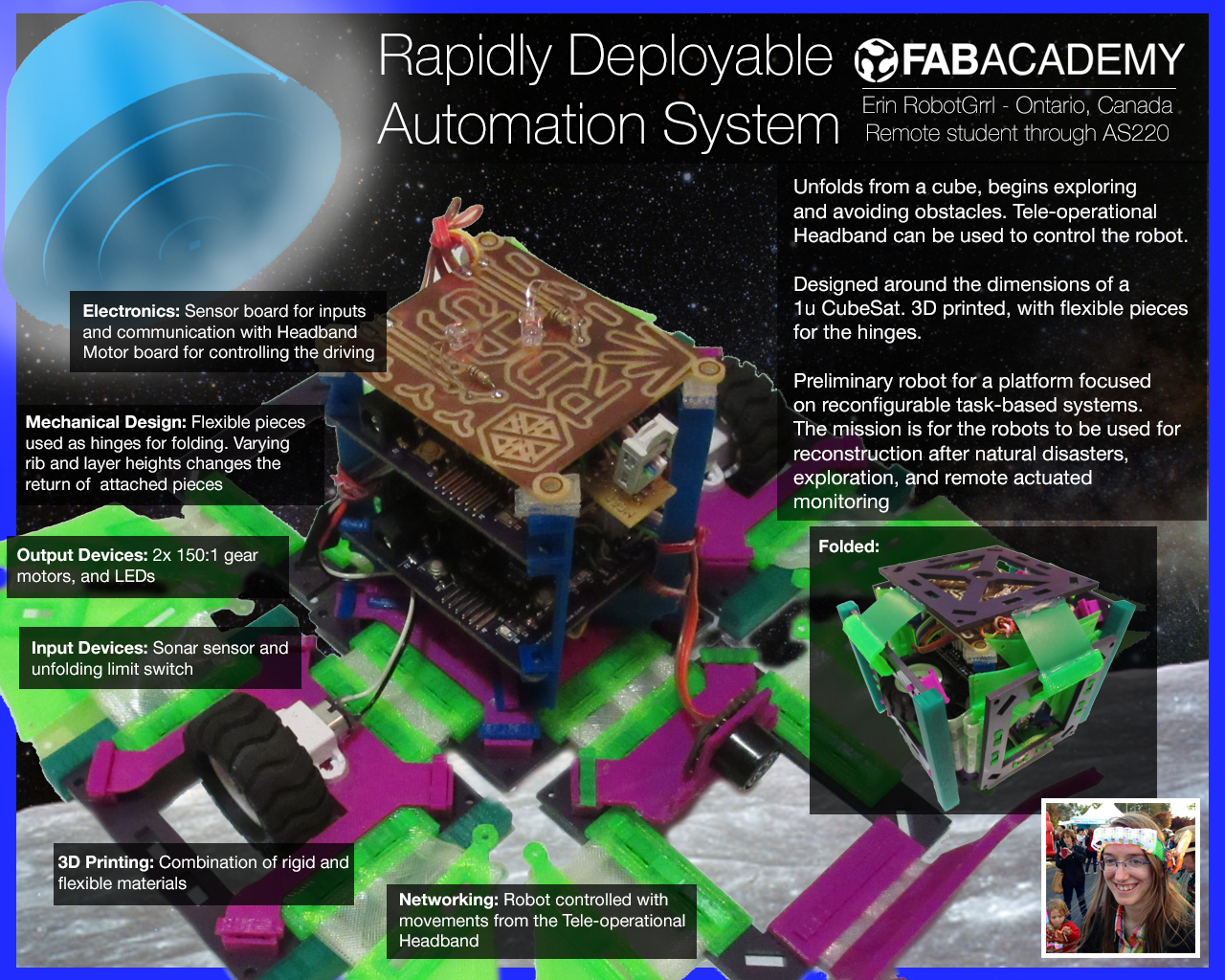
How it works
The robot is unfolded from its transportation cube shape. The green pieces will eventually be solar panels to harvest some energy. The sides with the wheels touch down and move the robot. The distance sensor in front detects and obstacles and avoids them.
Tele-operational control from the human is possible with a hands-free wearable headband with haptic feedback. The headband tracks the movements of the human's head and moves the robot accordingly.
Problem
Continuing from the description above, these robots are meant to be able to do tasks in parallel with the human. This way they can focus on more complex jobs.
Being able to achieve the level of parallelization is a key part to the problem; the robots won’t be very helpful if they have to be controlled all the time. They have to be able to do their task as autonomously as possible and when there is human input they have to understand what is trying to be communicated.
The goal of this is to eventually get the robots out in the field helping. It will take a long time with a lot of failures to get to that point. It’s all with another moonshot in mind: if the robots will be good enough for Earth, then what is stopping us from making them good enough for other planets as well. The robots could be tasked with starting to build structures on Mars, or go exploring, try to grow a plant (challenging in difficult environments).
Applications
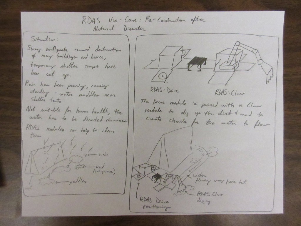
* Reconstruction after natural disasters
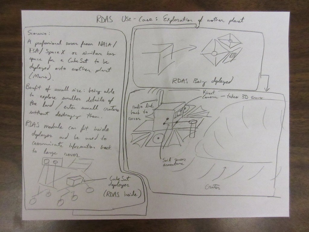
* Exploration
* Remote actuated monitoring
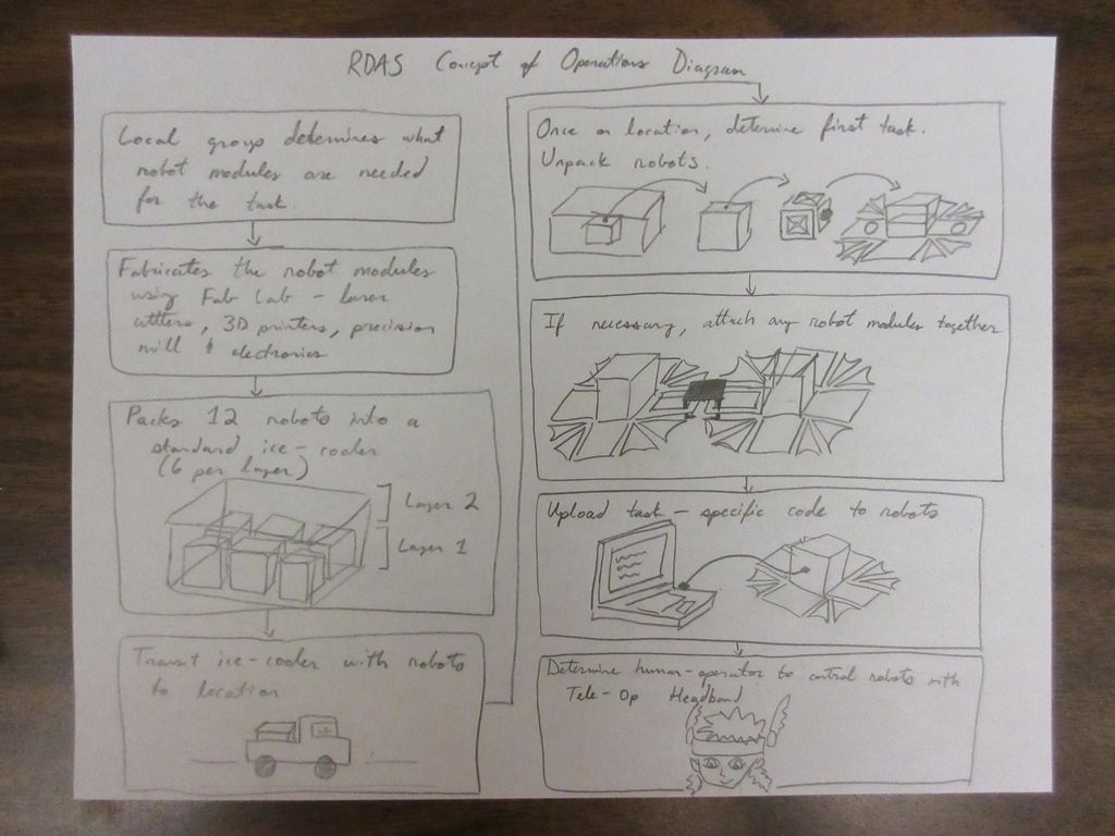
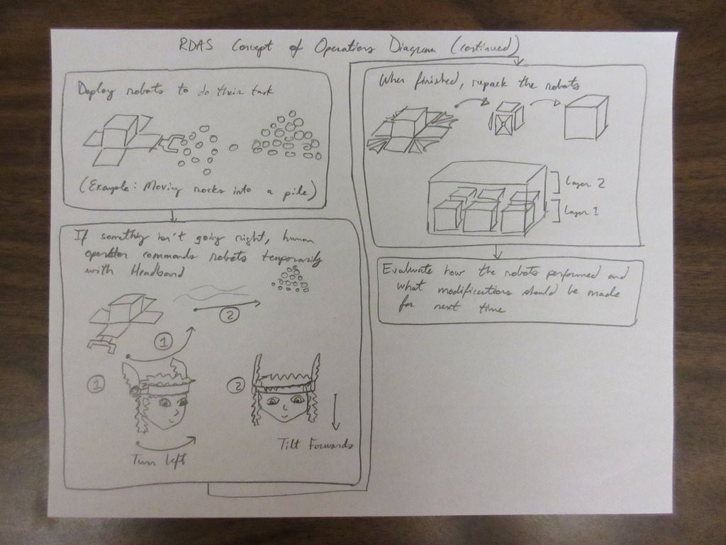
Concept of Operations
Click here for larger version of diagram 1
Click here for larger version of diagram 2
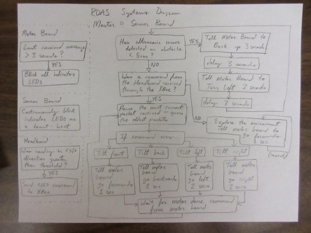
Systems
There are two main systems in RDAS:
* Motor system
* Sensor system + communications
Systems diagram click here for larger version
Example Application Diagram 1
Click here for larger version
Example Application Diagram 2
Click here for larger version
Developers
Another one of the goals of RDAS is to have groups developing on it, so that the robots could be deployed locally if there is a scenario where the robots can help. The experience could then be shared globally and go to all of the other labs working with RDAS, to improve an action plan for how the robots can be used to help in various scenarios.
Milestones
There are a few milestones to hit before getting RDAS into people’s hands:
Generic RDAS Chassis Design
The first of which would be to create a generic RDAS chassis, based off of the CubeSat dimensions. The work done here with making RDAS Drive module is helpful towards going to this milestone.
Field Testing
The ultimate tests will be to see how well the robot modules perform outdoors, in the real environment. It has to be able to work! Trying, failing, fixing things, will be the way this milestone is accomplished.
Weather Balloon Payload
Here is a goal along the horizon that I am racing to try to meet. That is evaluating the performance of the robot as used in a weather balloon payload. This would introduce it to different temperatures and conditions, as well as test how the robot can function at a high altitude.
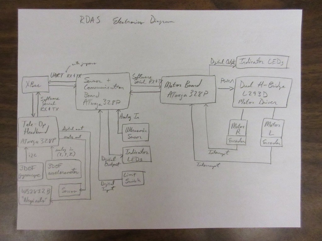
Electronics
RDAS uses a Motor board and a Sensor board, here are both Bill of Materials
Motor board:
Sensor board:
Electronics diagram click here for larger version
Structure
Download the .stl and Autodesk Inventor files here
Follow the Bill of Materials here for how many pieces to print and suggestions on how to print
Assemble the chassis- Scroll down to the "Assembling" heading here for a rough guide
Programming
The code for the Motor board is here
The code for the Sensor board is here
Note: This code was for the boards that were hand soldered with wire wrapping wire and perf board, so the pinouts in the code will be different than the pinouts listed in the BOM for the pcb boards
Optional: Tele-op Headband
This step is optional- if you want to make the Tele-op Headband to control the robot!
Download the laser cut pieces template
(Note: Some of the pieces need to be duplicated, refer to photos on this page)
The Autodesk Inventor files are available here
Details about the material + laser cutter settings, and rough assembly procedure is available here
The code is available here
Project Logs
Much of the initial prototyping was done through Fab Academy
http://fabacademy.org/archives/2015/na/students/kennedy.erin
Physics:
Research:
Mechanical:
- Video update: Panels, they can fold inwards now!
- Video update: Adding on the extension panels, getting ready for motors!
- Wheel Improvements (with 4 Elastic Bands!)
Electronics:
Licenses
The code will be licensed under the MIT License
The hardware, when it reaches a stable version, will be released under the CERN OHL license
Documentation will be CC BY-SA