 Johnny
The first thing I did was inspect the existing controller and tried to get an understanding of the existing system.
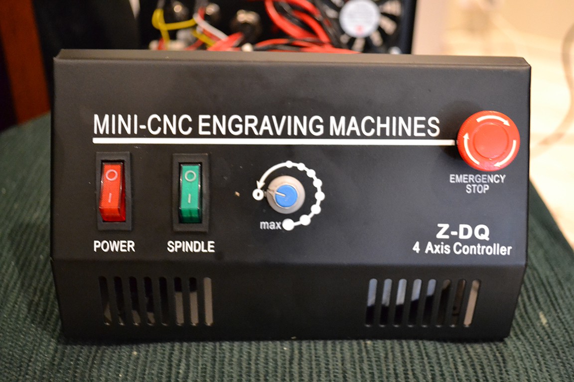
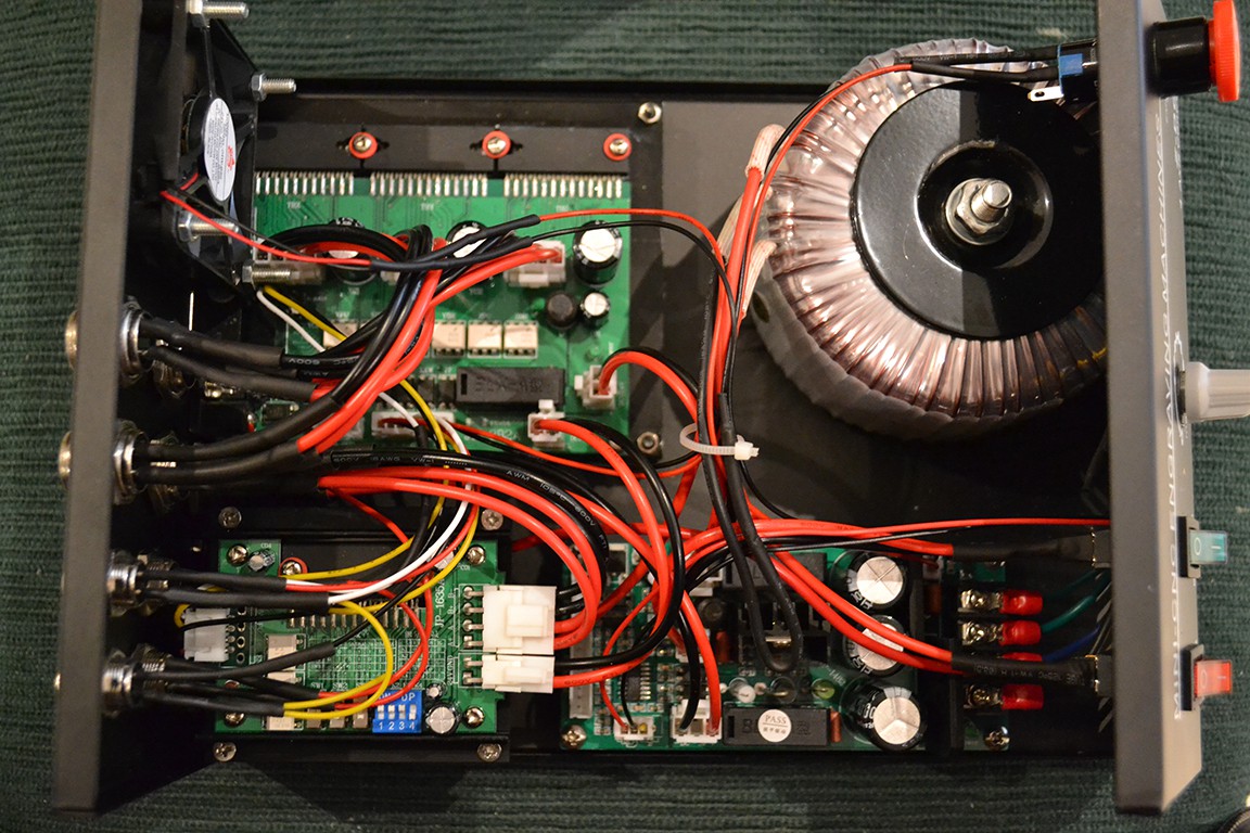
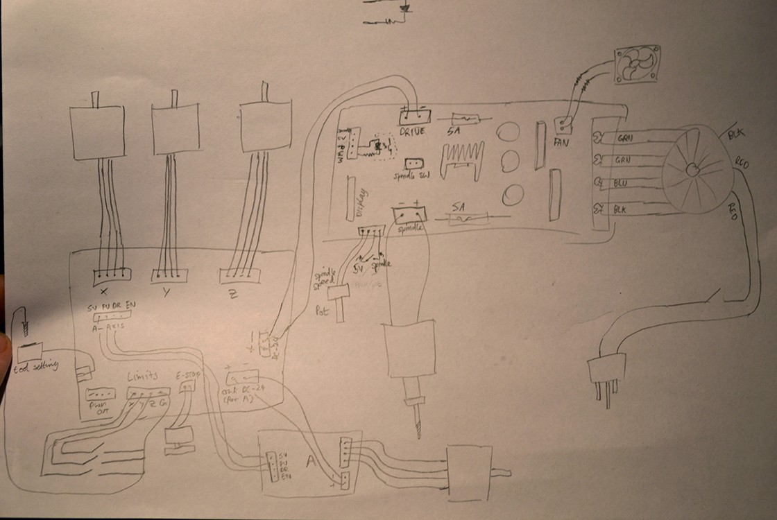
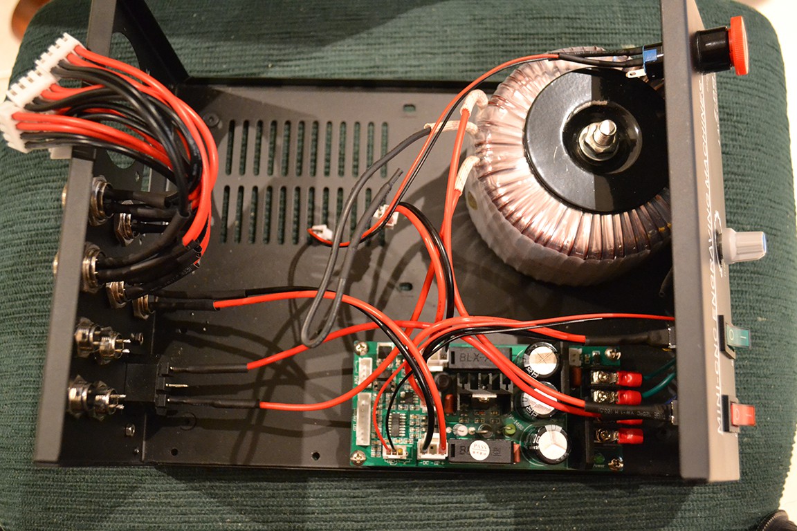
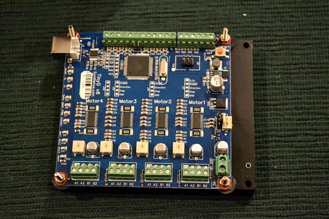
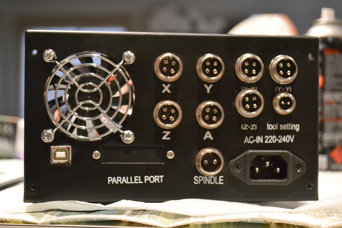
As you can see, the controller has three PCB boards inside. A 3 axis stepper controller (JP-382A), 4th axis controller (JP-1635A), and combined power supply and spindle controller (JP-1482). The controller box also has limit switches for x, y and z. Unfortunately they are wired in parallel, so the TinyG would not know the different between hitting the min or max limit on different axes (useful for homing).
Next I removed the fan, and stepper controllers.
Next I marked where the USB will poke out the back, drilled a hole and filed the hole square.
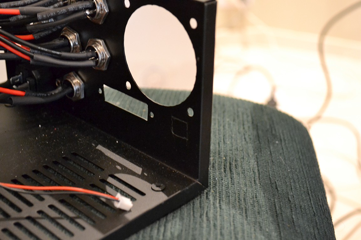
Here's the result.
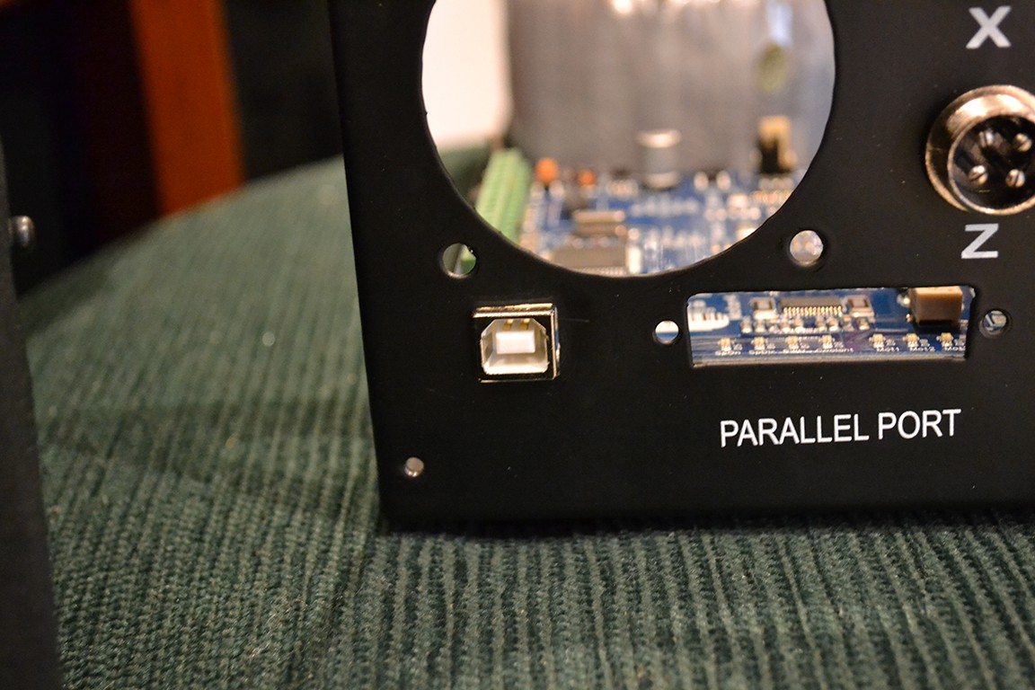
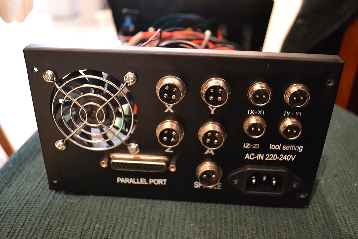
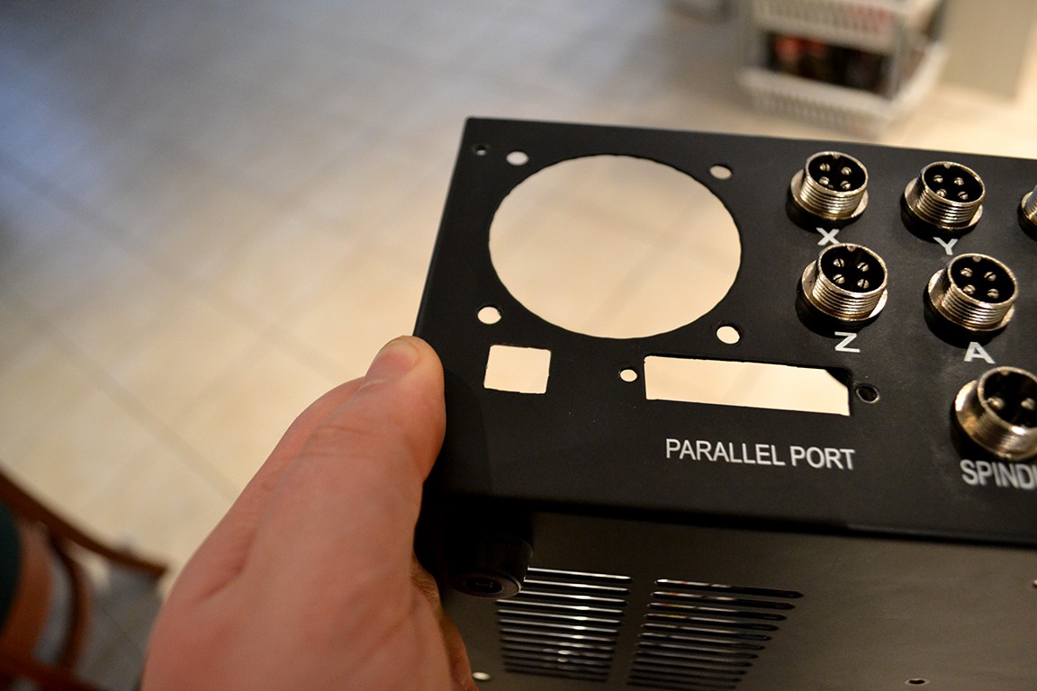
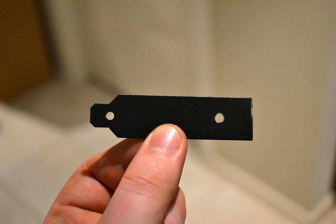
Next I made a cover for the parallel port hole using a blank PCI-e slot cover.
The next step was creating larger holes to fit 4 way aviation connectors to accommodate for new limit switch setup. That is, limit switches for min and max. To do this is used my Proxxon tool (like a dremel).
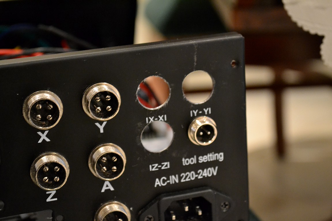
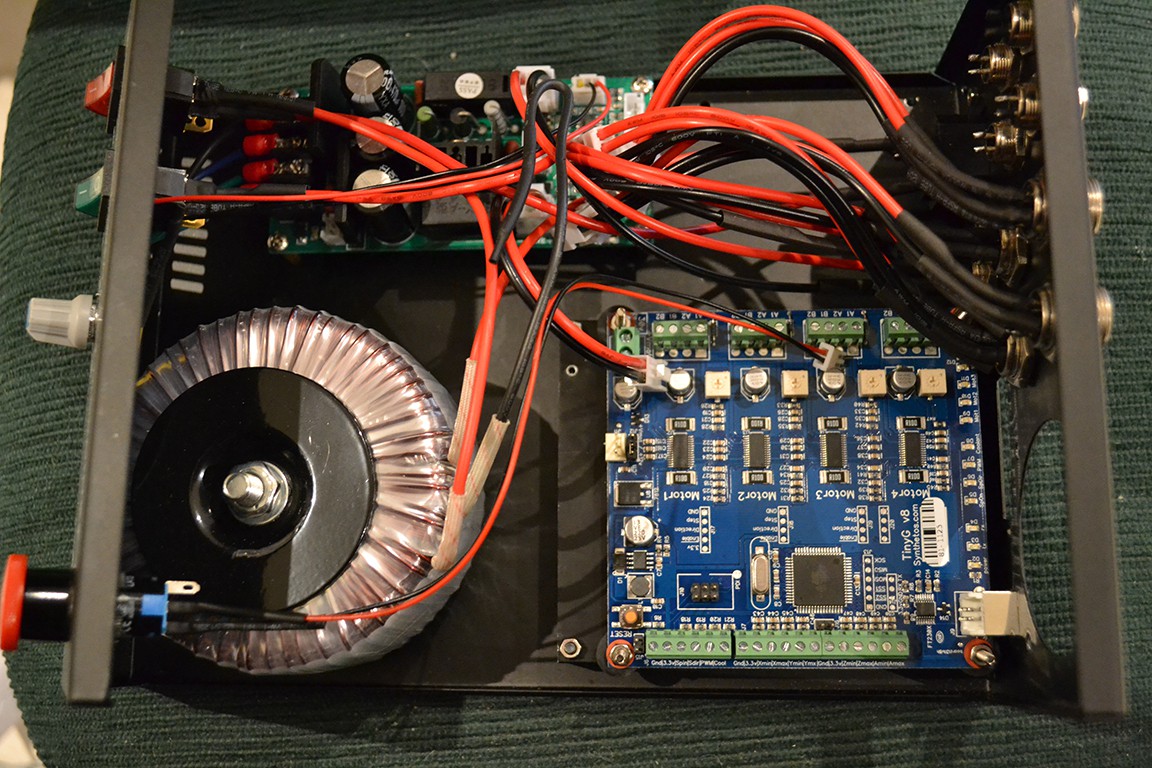
Finally I put some anti-rust paint on the cut surfaces (because this enclosure is steal and will get cancer) and installed the new connectors.
Discussions
Become a Hackaday.io Member
Create an account to leave a comment. Already have an account? Log In.