Charles Ahrens
-
Tube Layout
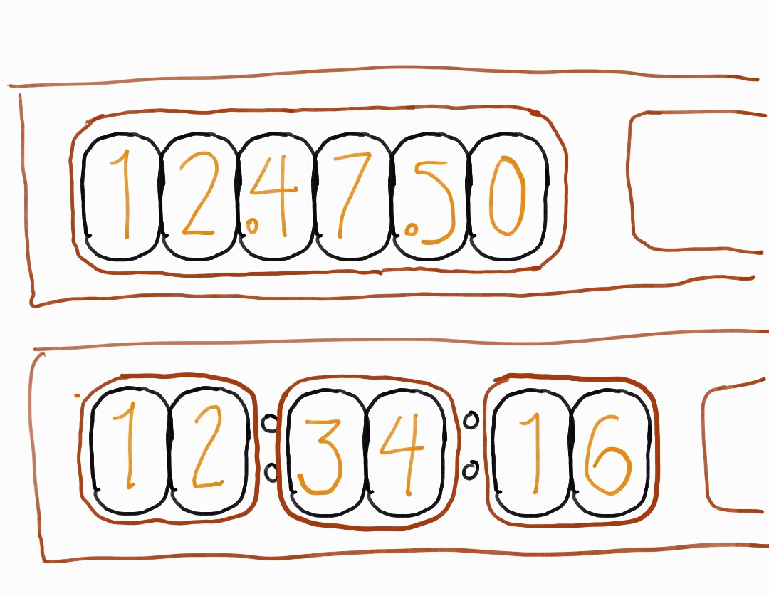
07/15/2015 at 07:18 • 0 commentsI decided to go with the 3 groups of 2 tubes for the front of the clock, since it will be easier to separate the hours, minutes, and seconds this way. I might change back to all 6 in a line in order to make the case easier to produce, though. I'm using IN-12B nixie tubes, so there is a little dot on each tube that I can access to make the hours, minutes, and seconds easier to tell apart.
![]()
-
Circuit Design
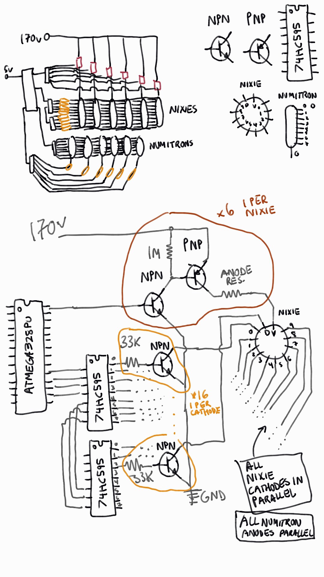
07/15/2015 at 07:27 • 0 commentsI designed the circuit to light the tubes as shown below, with daisy chained Shift Registers (74HC595) connected to the High Power NPN Transistors (MPSA42) to each cathode of the Nixie tubes so that the high voltage could drain through the tube, through the transistor, and to ground without frying the ATMEGA chip I am using to control it. I will connect all the cathodes of each Nixie in parallel (tube 1's 5 connects to tube 2's 5 to tube 3's 5, etc.), but the anodes to separate control circuits in order to multiplex the tubes. For the numitrons, I intended a very similar circuit, where all the anodes of each tube are connected in parallel, and the common cathode is connected to ground when I want to display on that tube. I also considered running each Numitron on its own shift register and daisy chaining them together, but I want to wait and see how the circuit works first.
![]()
-
Shift Register Woes
07/15/2015 at 07:34 • 0 commentsI had originally designed the circuit with 7HC595N Shift Registers (my favorite "default" shift register) without considering the large current required for the Numitron tubes. I had intended to either multiplex them or have all 6 tubes displaying at once, but even a single tube displaying a single number would be ~100 mA, which was waaaaaay more than the poor little 7HC595N shift registers could put out. Not to mention that the ATMEGA chip can only sink about 200 mA max on each ground line. I wouldn't have noticed this problem at all and probably fried at least one of my shift registers had I not noticed that each number displayed on the Numitron in a test circuit was a slightly different brightness. A number such as 1 would be super bright, since it was only 2 segments lit, whereas 8 would be super dim, since all segments were lit. In frustration, I began my search anew, after having already purchased 10 of the 74HC595s to use in the circuit.
Someone online at one of the Arduino forums had figured out that a TPIC6B595N shift register with high current capabilities could easily sink enough current to handle a Numitron tube. The only problem was that any shipper in the US charged about $5 per chip with quick shipping, and any shipper in China had slow shipping, but ~$0.50 per chip. I went with the Chinese seller, and was pleasantly surprised with the quick shipping. Now I just need to redesign the circuit so that I can use the 74HC595s for the Nixies and the TPIC6B595Ns for the Numitrons. -
Power Supply to test Nixie Power Supply
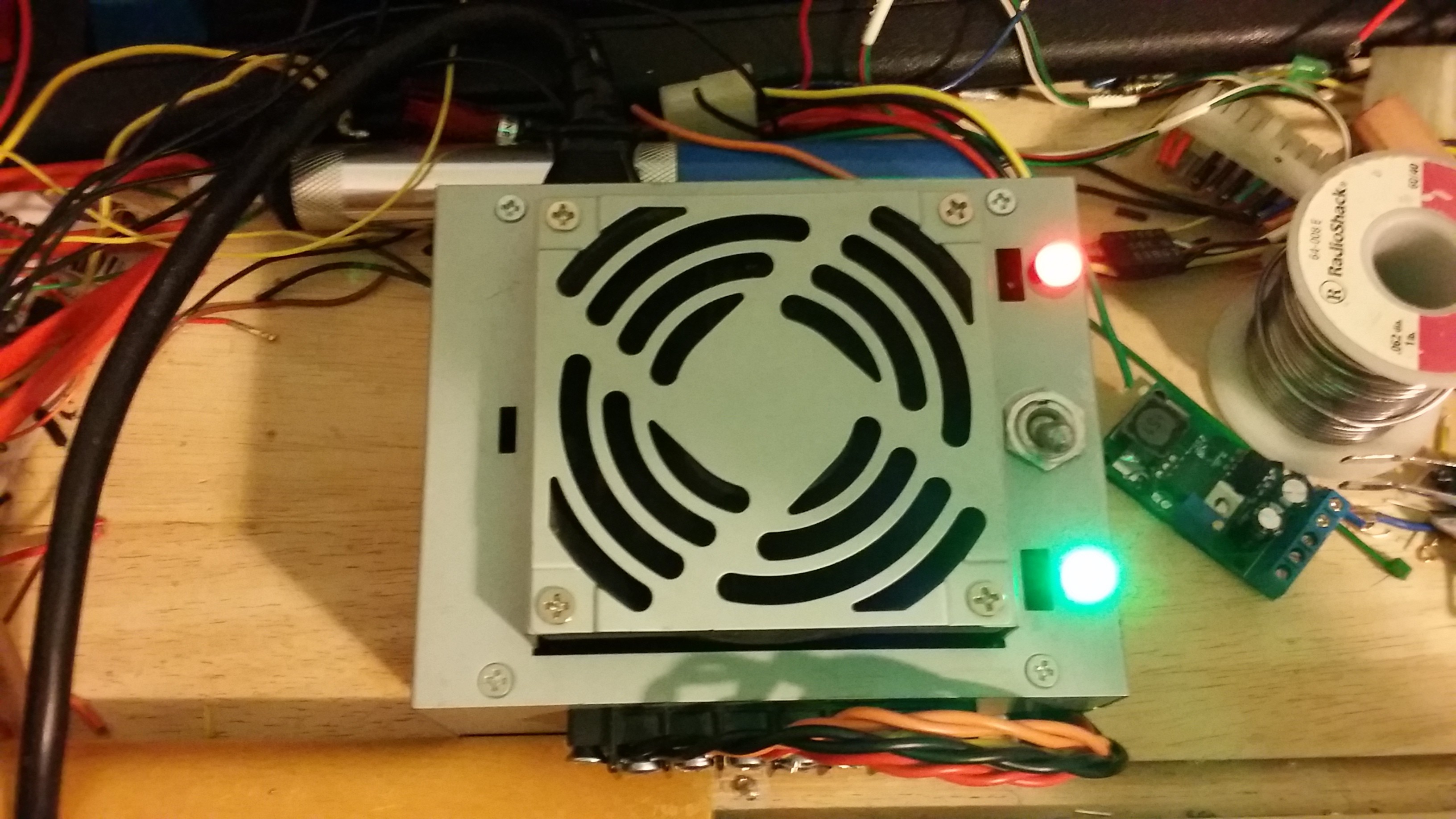
07/15/2015 at 07:47 • 0 commentsI needed to test the Nixie Tube Power supply, but I didn't have any 12V wall plugs, so it was the perfect excuse to finally finish my ATX benchtop power supply so that my little desk top circuit lab could have a decently regulated 3.3V, 5V, and 12V source (not to mention Ground and a bonus -12V). I followed a tutorial from this great video (I am not affiliated with them at all, it's just an easy to follow guide), where he does a very thorough walkthrough on creating a nice bench top power supply out of an old ATX power supply. I used a red LED on mine to show that it had AC power connected, and a green LED to show that it was switched on and delivering power to the screw terminal. I accidentally shorted out the first power supply that I attempted to do this to, because I forgot to connect the ground from the AC adapter back to the ground on the bottom of the power supply and I moved the top shell into contact with one of the heatsinks inside, shorting out the power supply and welding the top of the case to the heat sink. It wasn't worth saving so I trashed it and used a second old power supply I had laying around.
![Completed ATX Power Supply]()
![ATX Power Supply Switched On]()
-
Nixie Tube Tests
07/15/2015 at 08:03 • 0 commentsI have begun tests to try and determine the best anode resistor for the IN-12B Nixie tubes that I have. I used a very nice calculator to try and determine a safe value for the tube to light up, but not to shorten the lifespan of the tube too much. According to the calculator, at 180v and trying to give the tube 1 mA (well below the max of 2.5 mA), a 10 kOhm resistor should be sufficient. When I tested it, the tube was very bright and had a little bluish glow around the orangeish pinkish number. It was difficult to photograph, but definitely there. According to some sites, it's nothing to worry too much about, and just a sign that the tubes were "ultra long life" prepared, by adding mercury to the gasses inside the tube. I'm going to try some other values of the resistor to see if I can get the tube to some sort of sweet spot where it is a good brightness. I might implement a Potentiometer in the final clock design to be able to dim the tubes at night, or I might add a photoresistor to automatically detect the dark and dim them. Or I might do neither and just get used to the brightness.
![]()
-
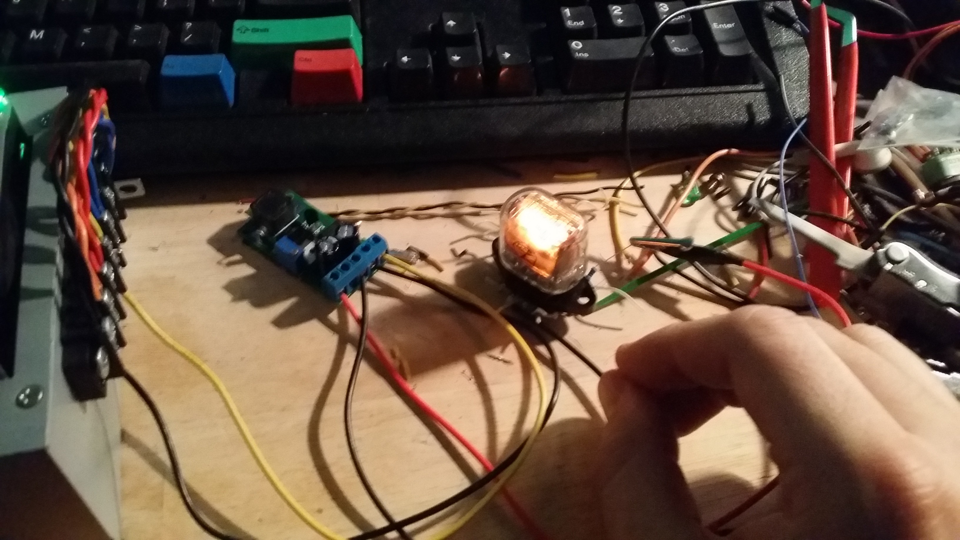
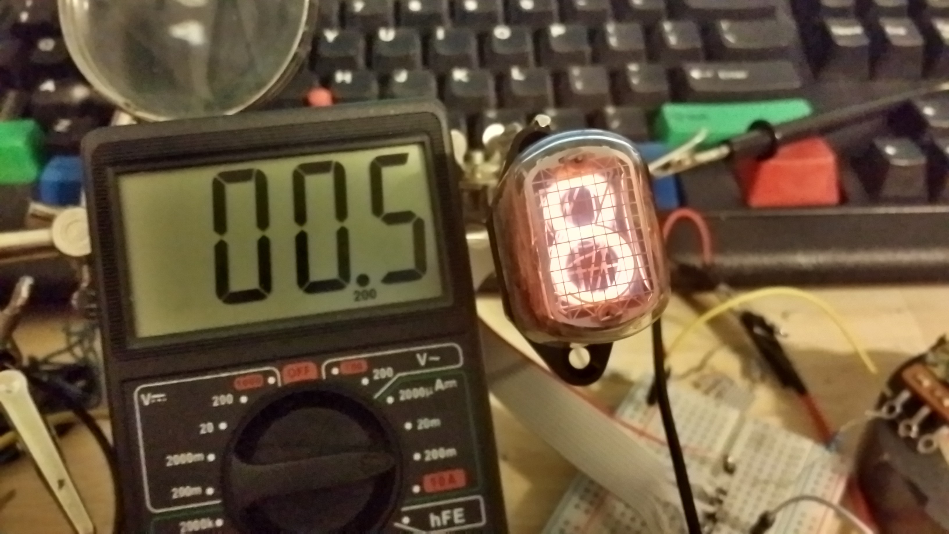
Wiring the First Nixie Tube
07/18/2015 at 05:16 • 0 commentsI wired up a connector from the IN-12 Nixie socket to breadboard header pins, with the pins in order for the digits on the tube. The high voltage anode was kept separate so that I didn't accidentally short anything while testing. I then tried to calculate the correct value of the anode resistor for the tube. I started with a supply at 180v and a 10k ohm resistor, but the current in the tube was just at the maximum value, around 3.6 mA, so I used a 100k ohm potentiometer to determine the perfect value. I started dimming the potentiometer until I reached a good brightness. 3.6 mA was too bright and I was worried about the tube, whereas 0.5 mA was too dark, and the number started getting fuzzy. Around 2.0 mA, the brightness was just right, and the number was crisp and readable. I measured the resistance and determined that a value of around 20k ohm would produce about 2.0 mA across the tube (or 2.2 mA with the decimal point and number lit).
![]()
![]()
![]()
![]()
![]()
-
3D modeling
07/18/2015 at 23:28 • 0 commentsI'm working on a 3D model of the clock in order to determine the style of the case, as well as the spacing of the tubes relative to one another. I had to start with the tubes and sockets and move on to the wood parts of the case. I intend to make the case out of several stacked pieces of wood (I have a lot of heart of redwood left over) with minimal complex cuts so that I can produce the case with mostly hand tools and my table saw. I'm using my student license of Autodesk Inventor to model all the parts.
![]()
![]()
-
Circuit Schematic and Transistor Tests
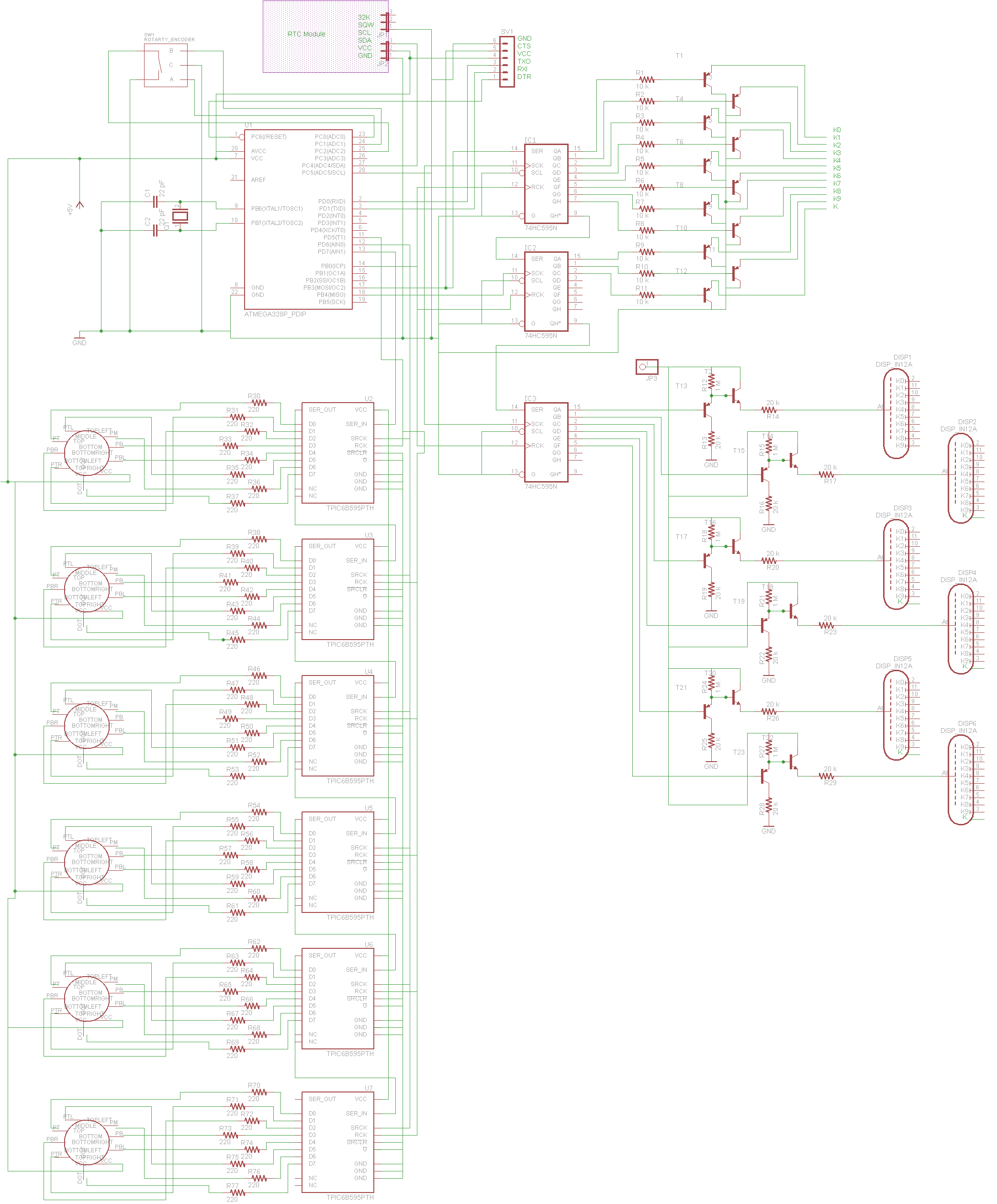
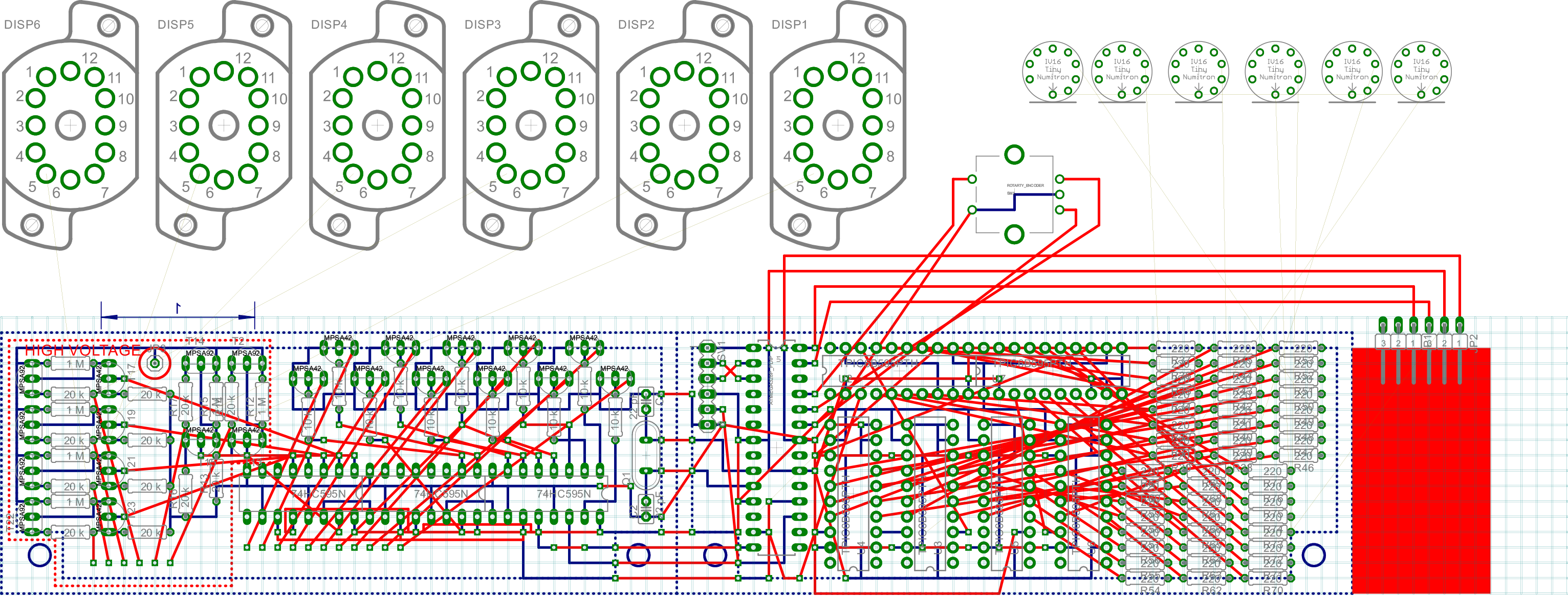
07/24/2015 at 03:58 • 0 commentsI wanted to create a circuit diagram in order to figure out how I was going to fit all the components on the circuit board and how they were all going to connect together. I don't want to spend the money to get a custom printed PCB, and I don't have the components to do my own toner transfer and etching method, so I will use a solderable perfboard to wire everything up.
![]()
As shown in the circuit diagram, the cathodes of the Nixie tubes will be run through shift registers connected to high voltage transistors that will dump the current to ground, while the anodes for the Nixie tubes are connected through another shift register and high voltage transistors in order to supply the 180V supply and multiplex the tubes.
The Numitron tubes, however, will all have their common connection to 5V, then the cathodes will be dumped through the high current shift registers. I have it designed to have 6 of these shift registers, but I might change that to have the Numitron tubes multiplexed as well. I'm not sure yet, I will have to do some tests to determine which method is better.
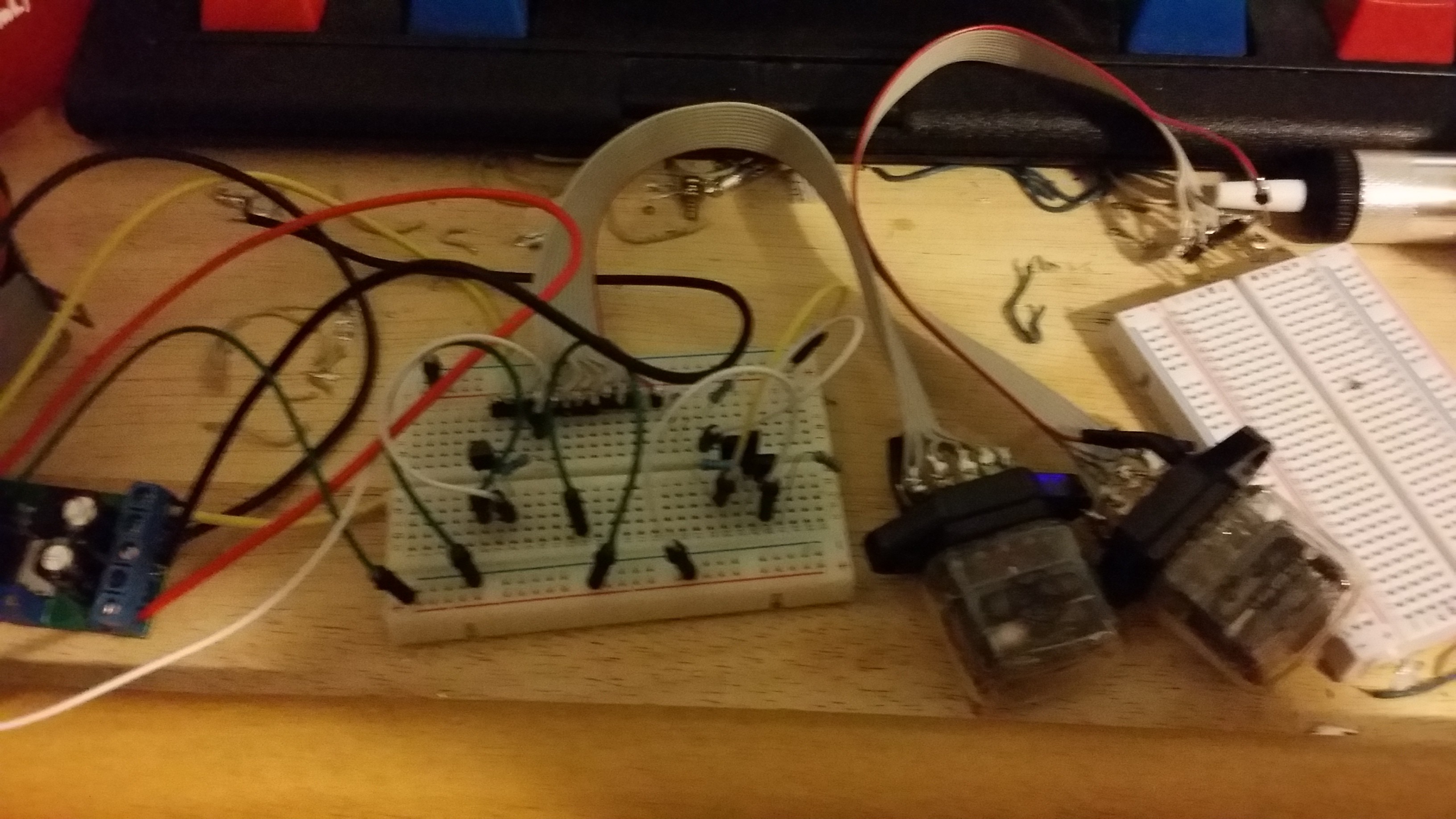
The test of the high voltage transistors is shown below. I wired these up with a 5V and a 180V power supply to check that the tubes would light with the correct anode resistor value, as well as not burn out either the transistors or any of the circuit. Luckily I ordered 25 of each MPSA42 and MPSA92 (NPN and PNP) so that I can have a few extra when I inevitably burn one out from faulty wiring.
![]()
Once I ensured that the circuit would work, I designed a PCB in EAGLE, with the intention of copying it to solderable protoboard with a sharpie and then soldering over it. I bought single sided protoboard, so the soldering will be on the bottom, and the top layer will have loose wires connecting the different chips and bridging gaps. As shown in the PCB, there will be only a single rotary encoder (with a built in button) to navigate the setting of the time, as well as enable me to switch between temperature display, day of the week, and date.
![]()
-
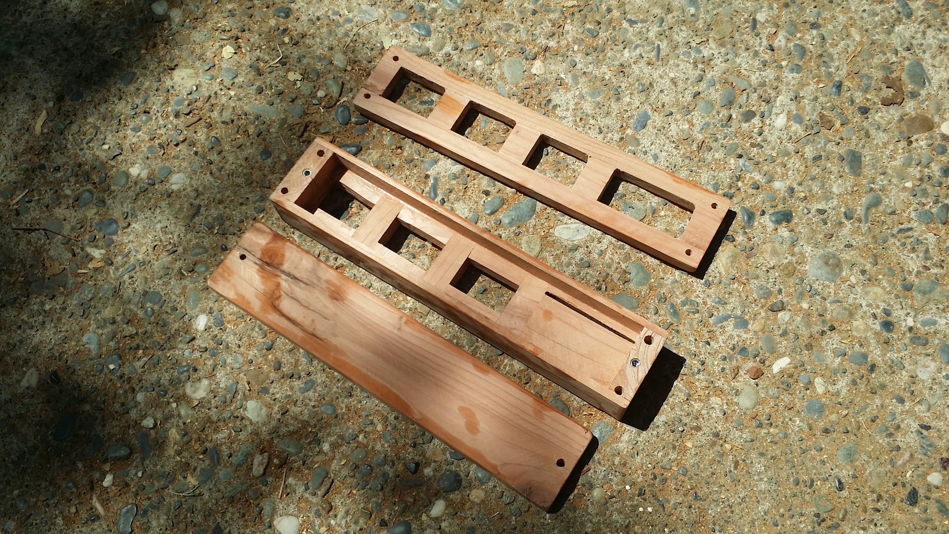
Woodworking
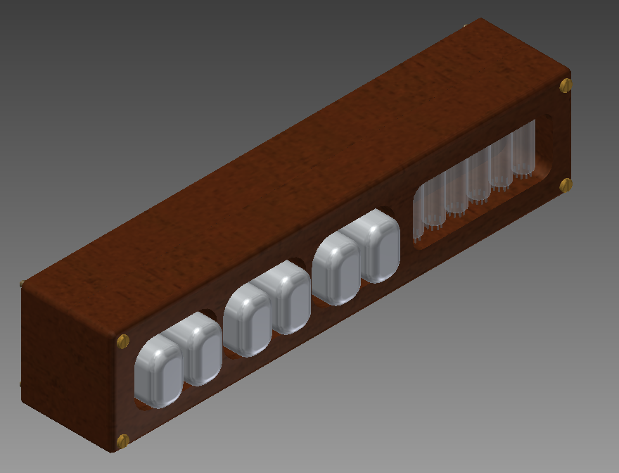
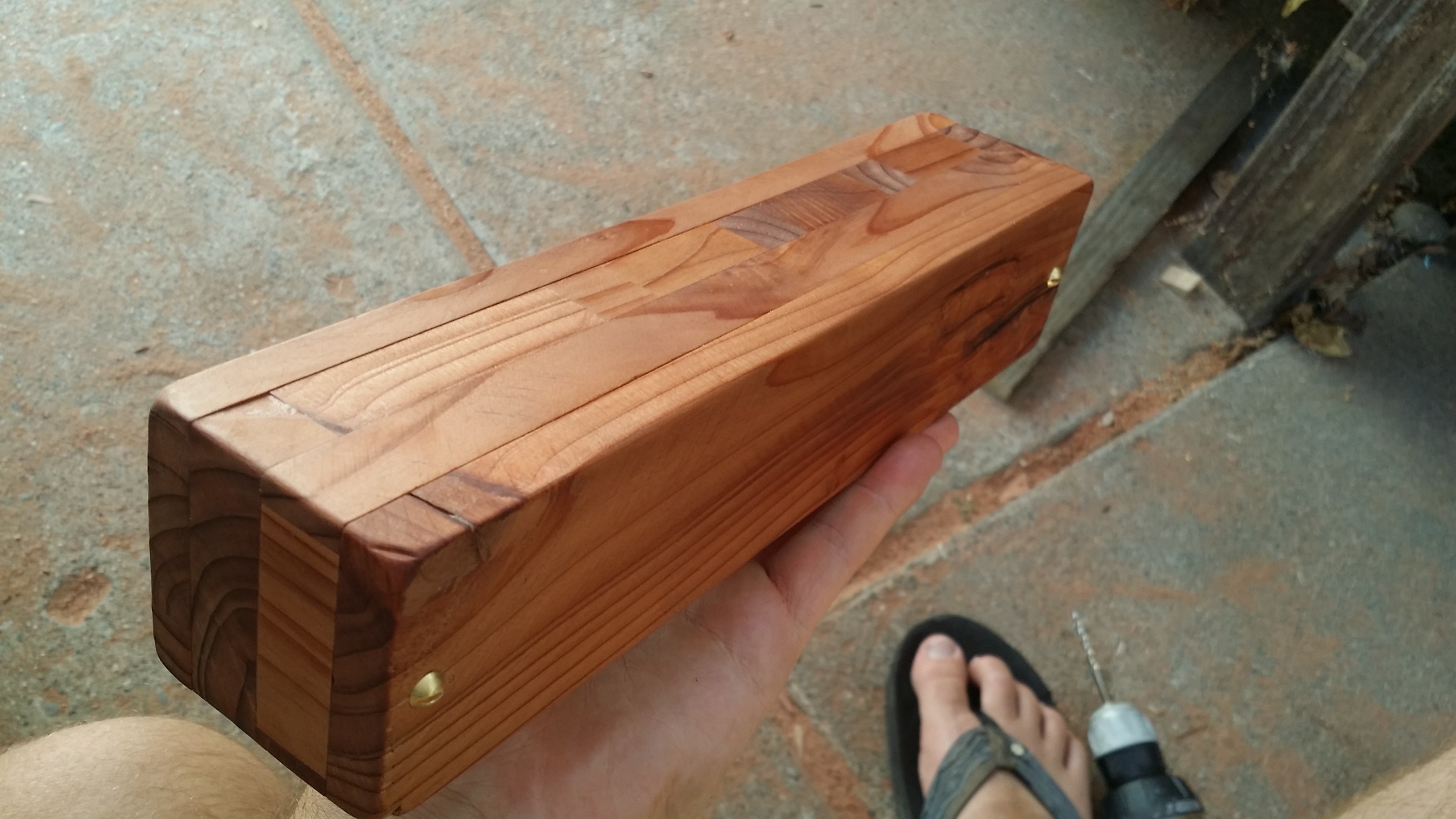
09/27/2015 at 03:21 • 0 commentsBefore I moved back across the country, I designed and built a heart of redwood case for the clock and set some machine screw wood threaders into the middle section so that the front and back plate could mount together without damaging the wood.
![]()
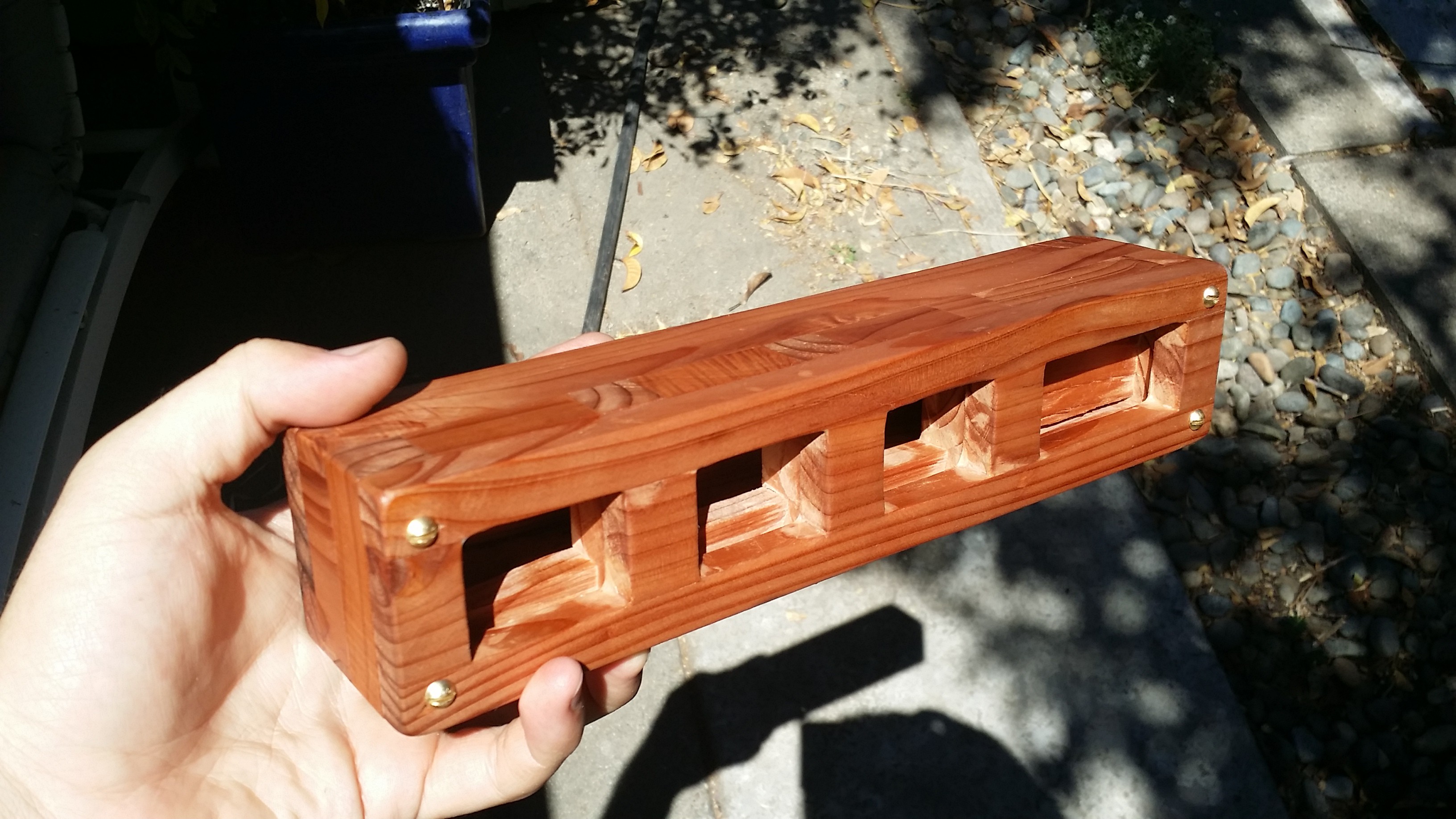
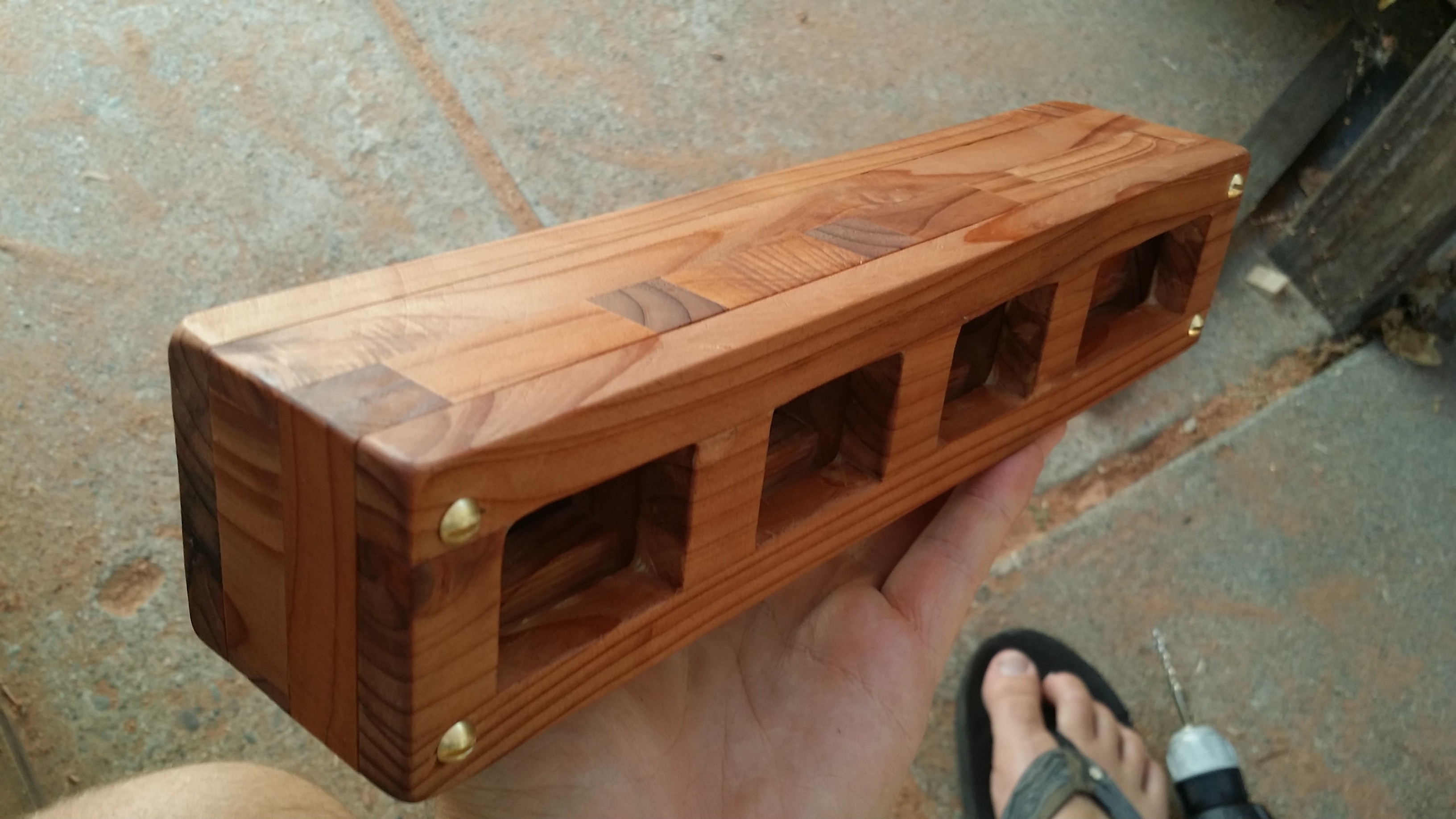
After I assembled it, I used a combination of mineral oil and beeswax to finish the surface to a nice sheen. It's soft and smooth, but not slick. I might do a few more coats to make it really shine.
![]()
![]()
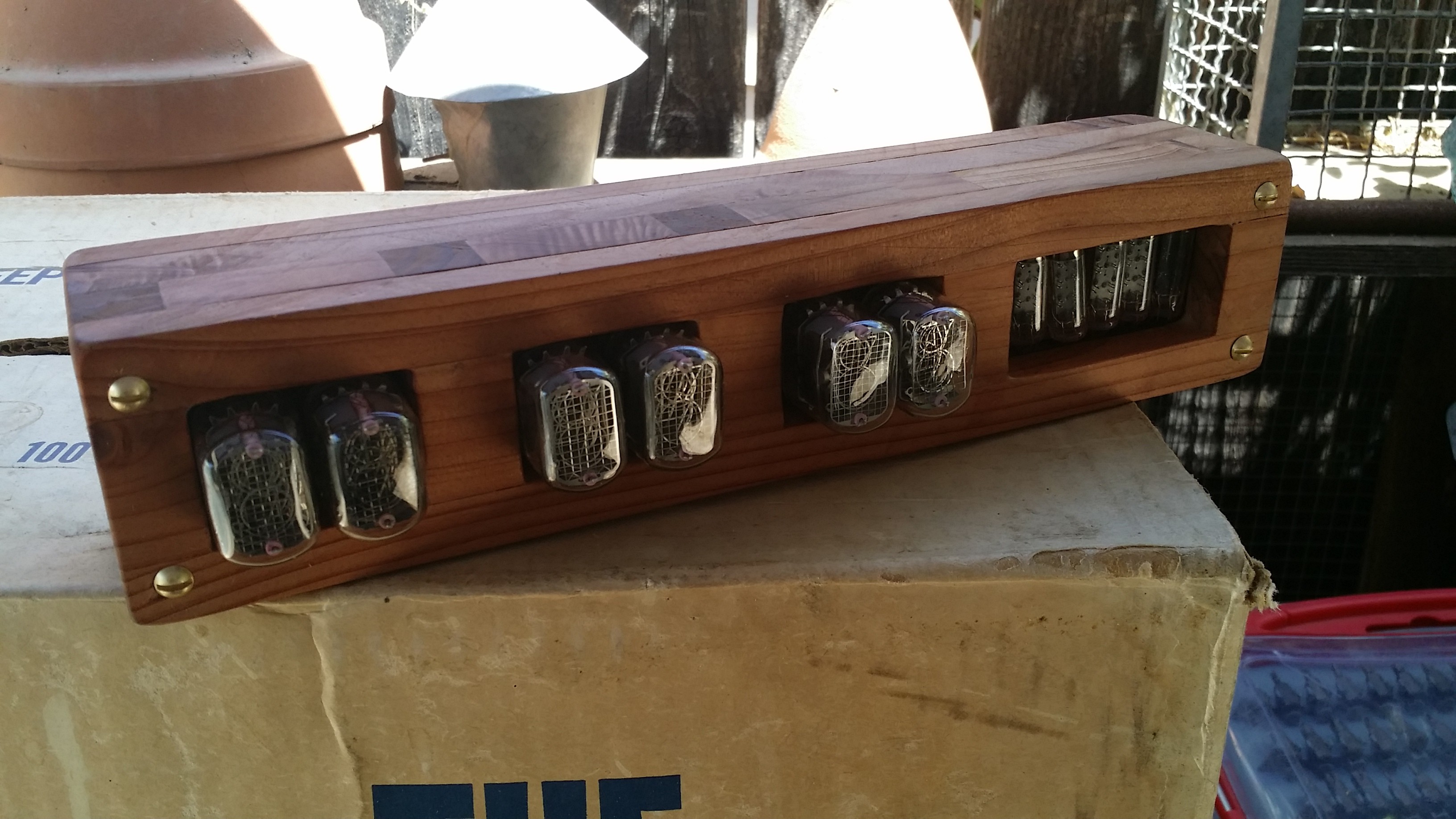
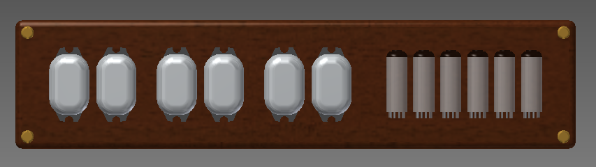
![]() This is the assembled clock with tubes in. Right before I took this, I dropped (and shattered) one of the Numitron tubes, so I will have to order another from ebay.
This is the assembled clock with tubes in. Right before I took this, I dropped (and shattered) one of the Numitron tubes, so I will have to order another from ebay.![]()
-
Knob and Power
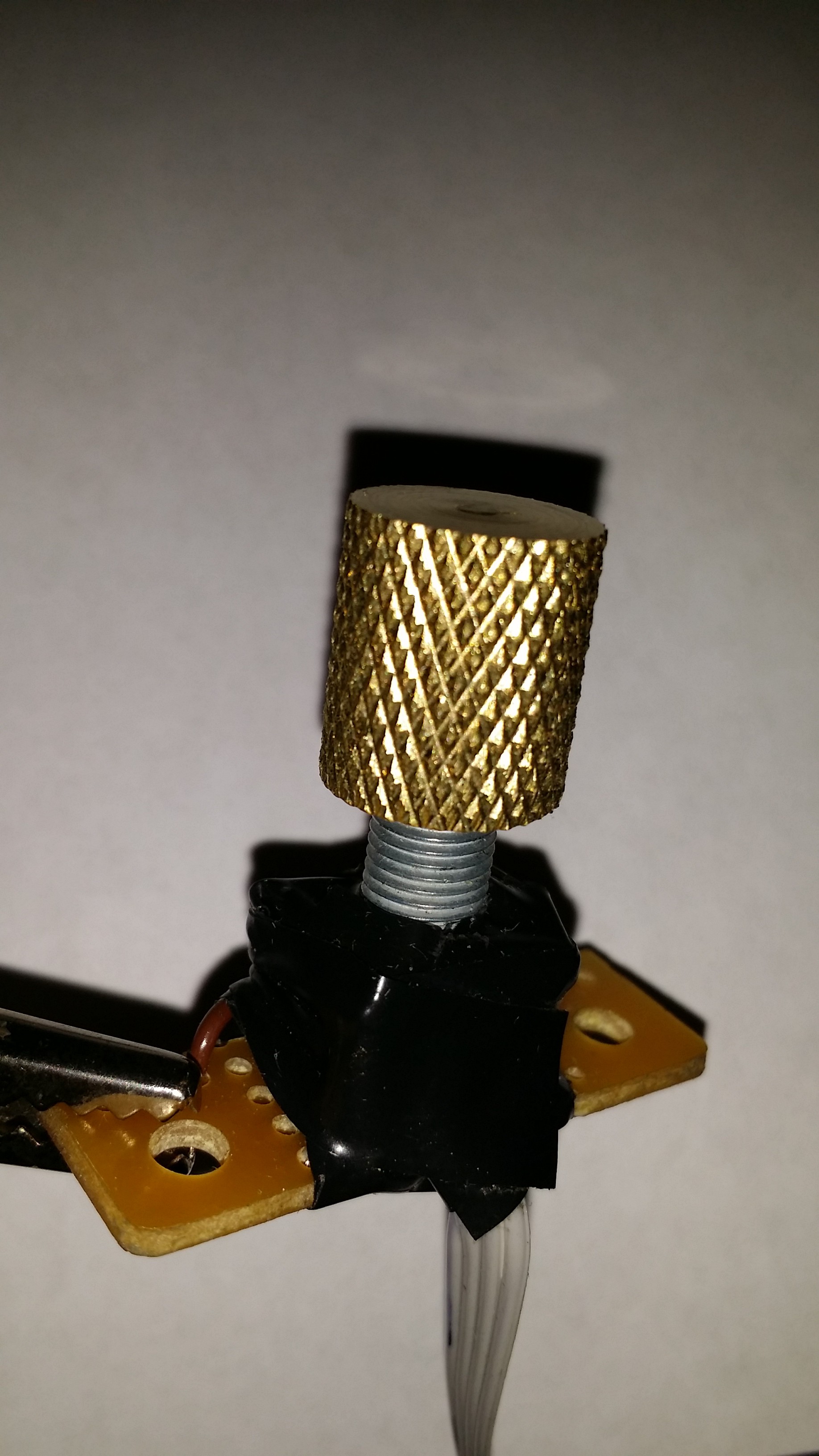
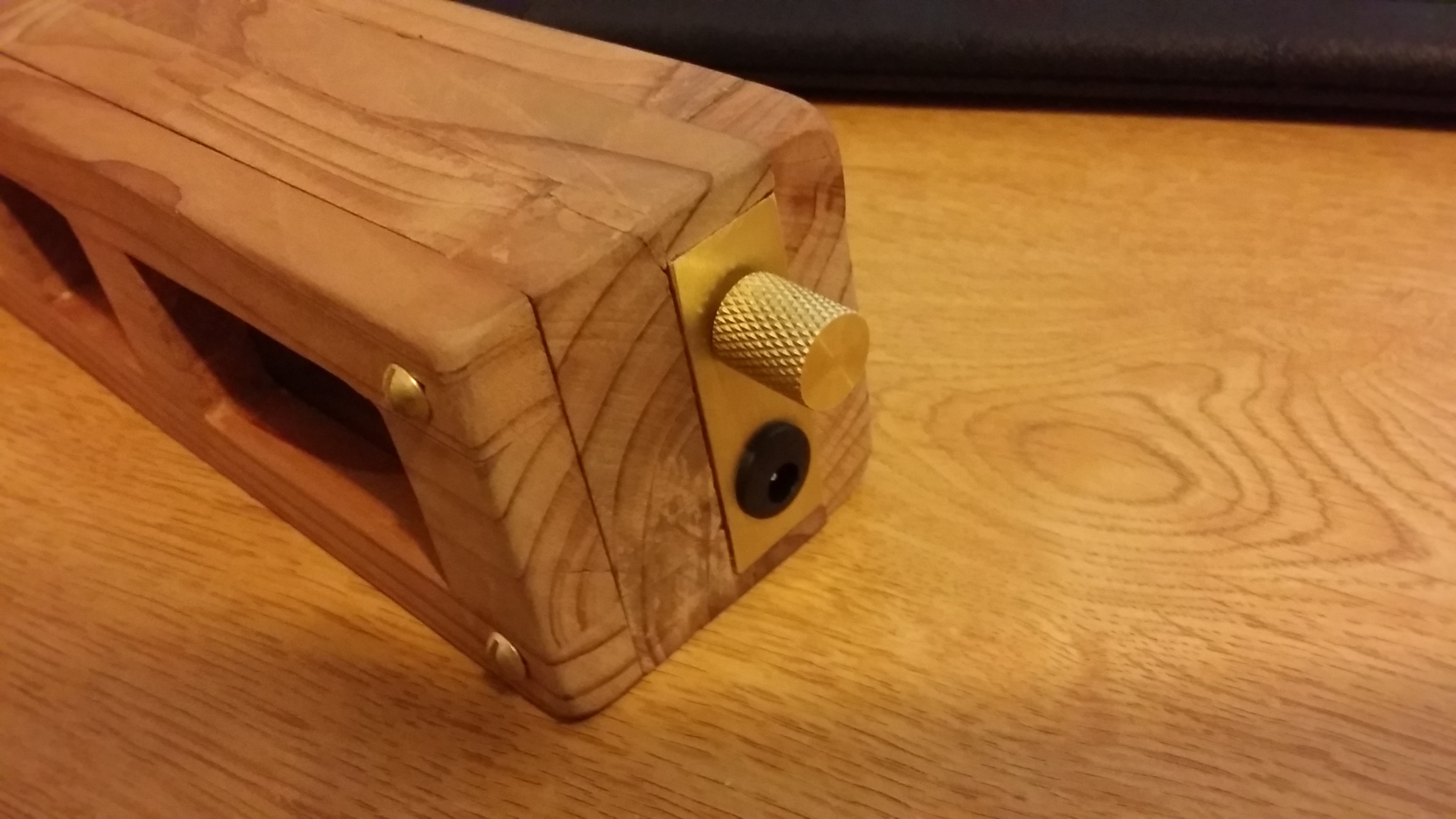
09/27/2015 at 03:43 • 0 commentsI decided on using a rotary encoder with a pushbutton integrated into it as the only source of control for the clock, to switch between the different modes (12 hour, 24 hour, date, temperature, day of the week, setting time, etc.) and I needed to machine a knob to fit the encoder since it didn't come with one. I used the machine shop on campus to lathe a small ~15 mm knob out of brass, with a brass plate that would hold the knob and power plug to the side of the case.
![]()
![]()
Nixie and Numitron Clock
Combining the retro awesomeness of Nixie tubes and Numitrons to make one cool clock.


 This is the assembled clock with tubes in. Right before I took this, I dropped (and shattered) one of the Numitron tubes, so I will have to order another from ebay.