 DrYerzinia
So I did the measurements on the power and I'll just get strait to the point here:
In direct sunlight it was charging at ~2mA. That works out to needed 7.2 minutes a day of direct sun to keep the device operating or for a full charge of the battery 5 hours of direct sun. So if your cat likes to sun itself for atleast 7.2 minutes a day or 5 hours a month you will never have to charge the collar. I measured about 80,000 LUX in this environment.
Alternatively on a sunny day the ambient light generates ~30uA of charge current. That's 3x the devices power requirement. So if the collar only gets ambient light 8 hours a day it should still be able to never need charging. I measured my ambient lighting at ~300 lux.
Those are the practical figures. Now I will go on telling the story of the adventure I had building and testing the circuit. First problem was fitting the bodge resistors on the board.
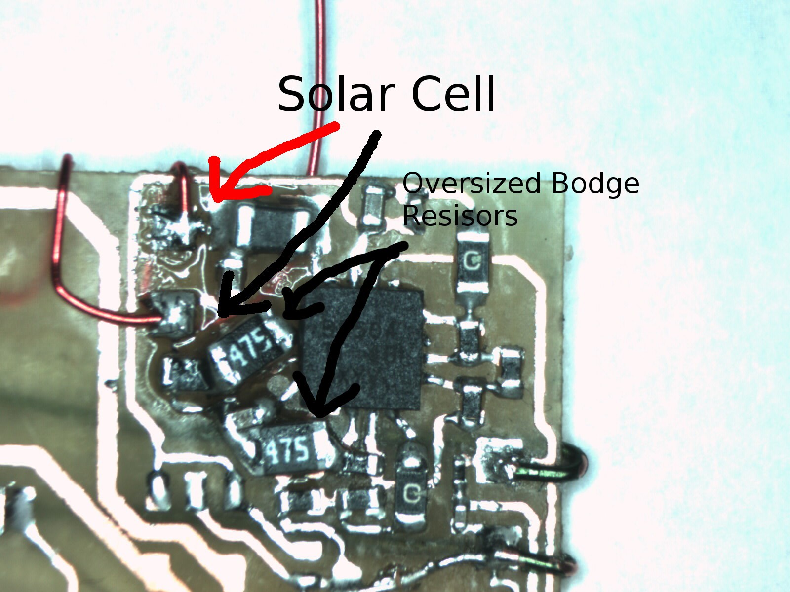
There not technically bodge resistors, just oversized ones because I forgot
to order the 0402's which will now be here on Saturday. I managed to barley get them in.
The next set back wasn't detected till I started probing the circuit. After applying sun to the cell I didn't get any boost conversion going. The chip wasn't loading down the cell and I got less voltage out than in!
So a quick look at the recommended application circuit schematic and I realized *DOE* I forgot a connection from VSolar to the VIn off the chip!
Time to add a bodge wire.
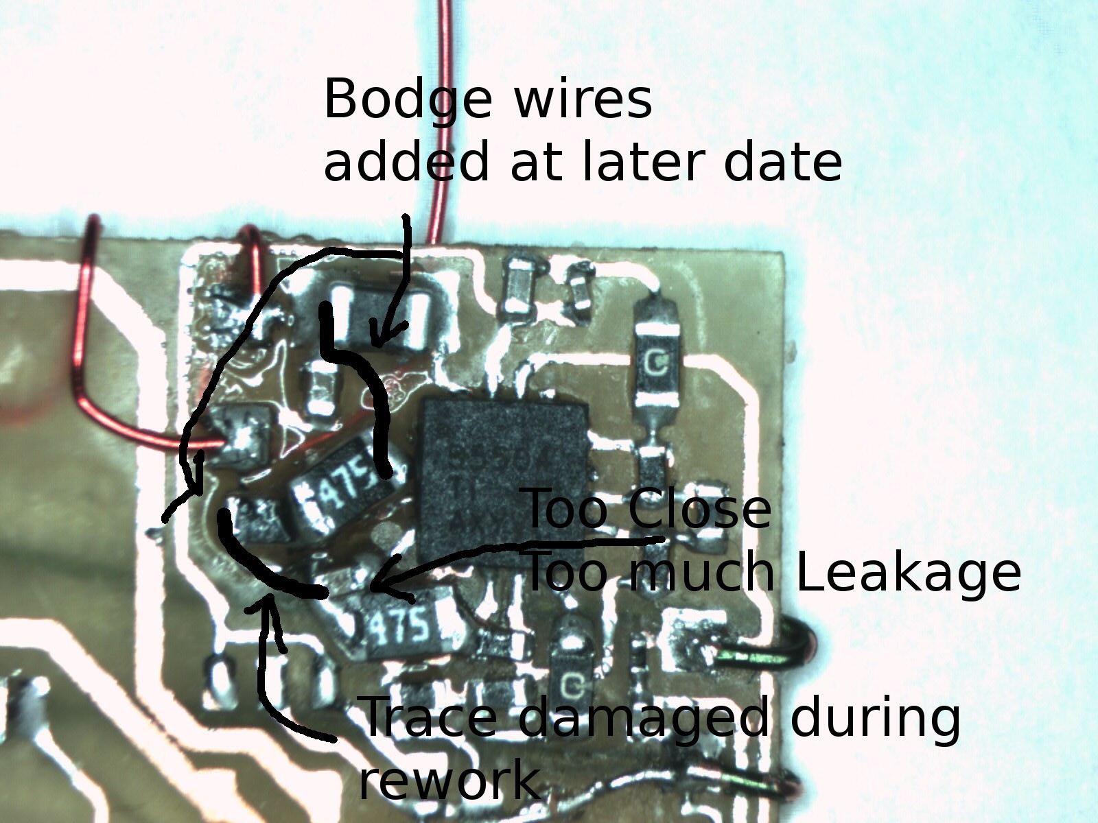
So I bodged in a wire from the resistor on the VIN to the inductor on the VSolar. And IT WORKED!
Only one strange problem, the voltage of the solar cell was oscillating up and down. Another trip to the datasheet and I understood why. The MPPT algorithm works on a 16 second cycle. It samples the unloaded solar cell voltage through a resistive divider which in this case give 73% of open circuit voltage and stores that in a capacitor for reference. Then feedback from that voltage its used to determine how much current to pull from the solar cell to boost its output to charge the battery. My first thought after looking at the circuit was just how very close that capacitor was to shorting back across itself to ground. And I did a bit of rework to move its important end to be more isolated. Broke a trace doing it and added another bodge wire.

Now that everything was working its time to test the circuit performance under real world lighting conditions the results of which are at the top of this post.
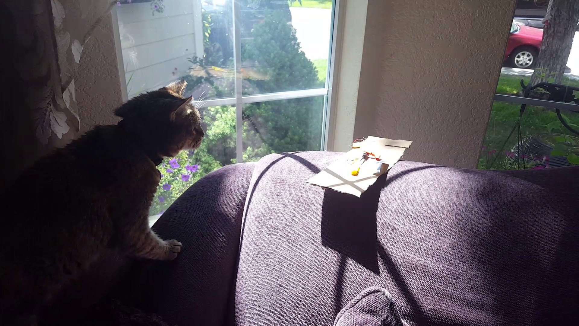
interference. Yes the tree got in the way for a bit. And with 80kLux
we get a charge of atleast 2 mA. Way more than enough to charge and run
the collar.
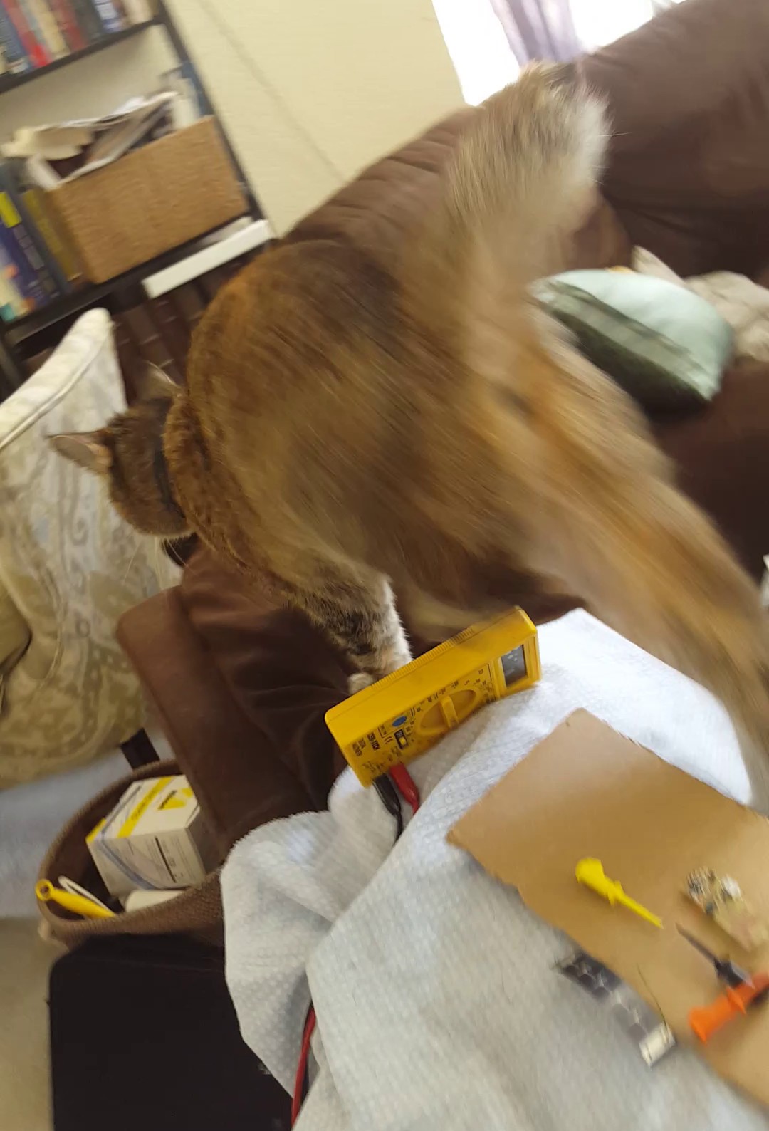
The next setup was on the back of the couch in the main TV room. The moment I started recording Fiona hopped up to check out what was going on and unexpectedly landed on the circuitry. Here I recorded 300 lux with my phone and a respectable 30uA current. Enough to run the circuit and charge at 2x the operating current.
I took away a few things from this experiment, first solar powered harvesting devices for radio networks have to be ridiculously efficient if they don't get direct sunlight. Ambient light at 300 lux is nothing compared to the raw 80000 lux power of direct sunlight. That's 260x more energy in direct sun! But thankfully with my designs 10uA current draw we can still pull it off with low light levels if we have to and as a last resort you can always charge the battery with micro USB.
Discussions
Become a Hackaday.io Member
Create an account to leave a comment. Already have an account? Log In.