 Thomas Flayols
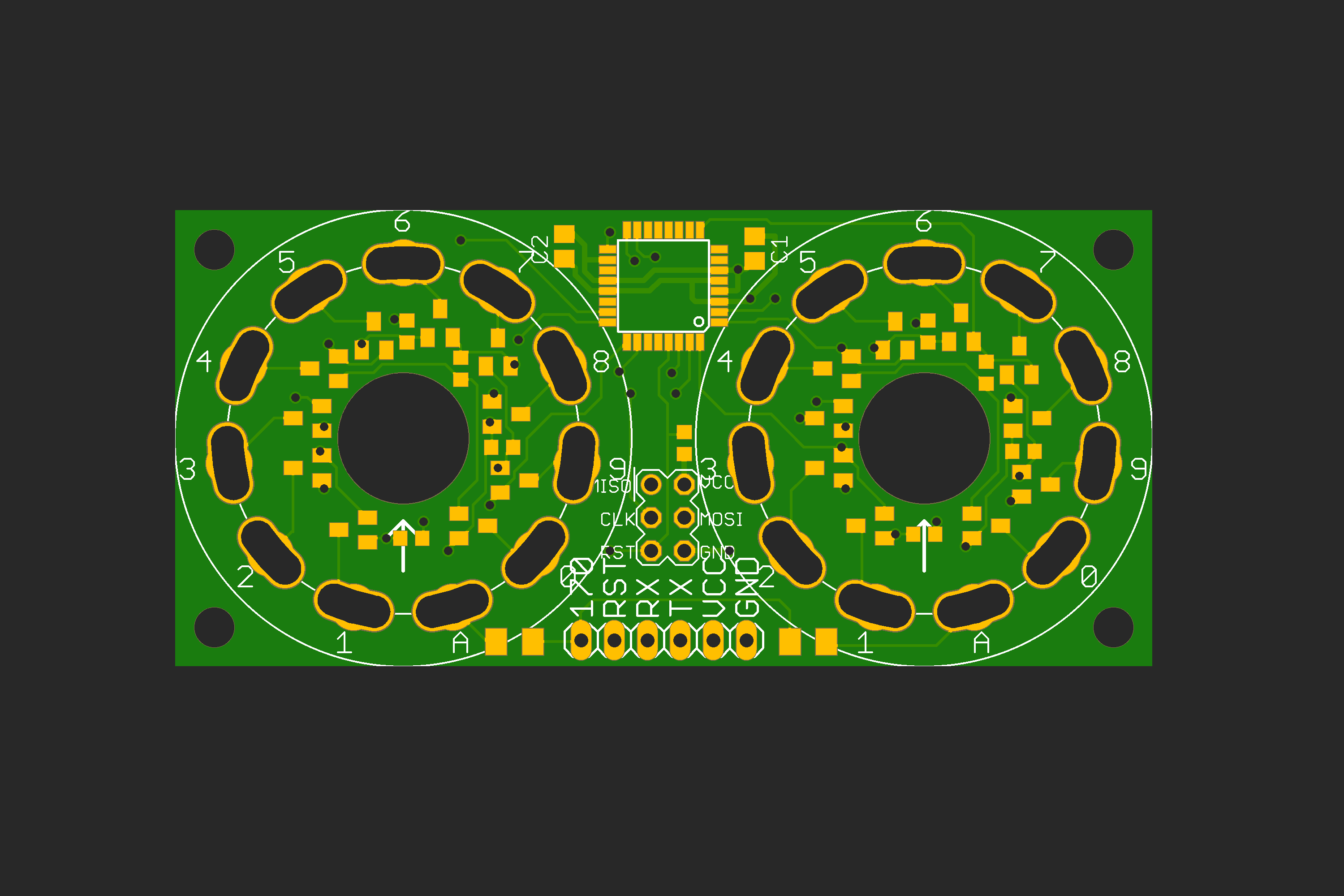
So here is a revision of the PCB, It addresses two major problems of the first design.
The anode resistances were 0402 sized, too small to dissipate a power of (P=RI² = 22k*2.5mA² = 0.14 W) They are replaced by 1206 (0.25W).
Second issue, some IN1 nixies have very bad alignments between numbers and pins. For example from another project here :
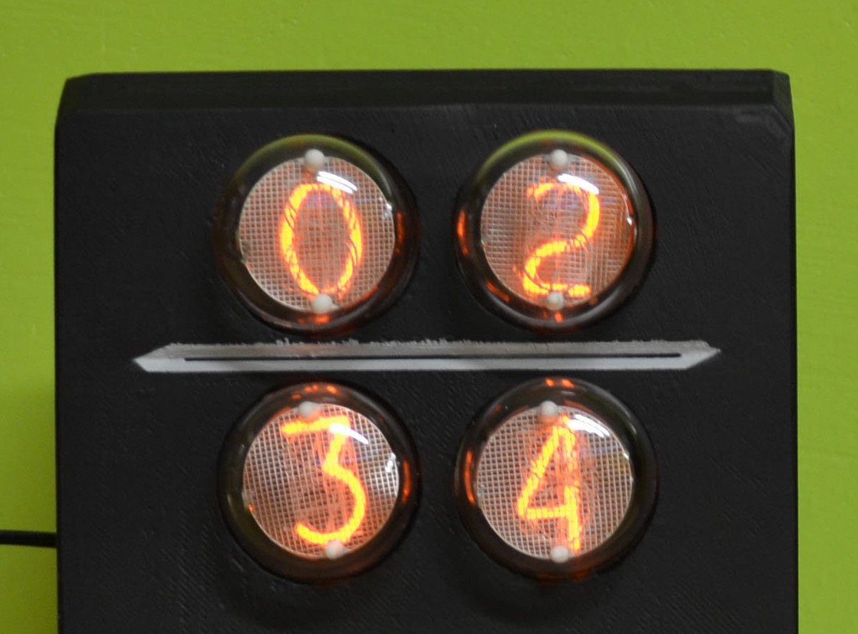
In order to compensate, I modified the tube footprint to have a little margin.
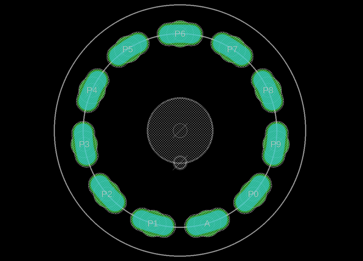
To do this with Eagle, I generated the commands from a python script:
# Script to do circular slots in eagle
from math import cos,sin,pi
arclen = 0.12 #rad
r=13.5 #mm
Nslots = 11
cmds = [";CHANGE LAYER 17 ;CHANGE WIDTH 3.0",
        ";CHANGE LAYER 29 ;CHANGE WIDTH 3.2",
        ";CHANGE LAYER 30 ;CHANGE WIDTH 3.2"]
for cmd in cmds:
    print cmd
    for i in range(Nslots):
        angle = i*2*pi/Nslots
        start_x = r*sin(angle-arclen)
        start_y = r*cos(angle-arclen)
        opp_x   =  -start_x
        opp_y   =  -start_y
        stop_x  = r*sin(angle+arclen)
        stop_y  = r*cos(angle+arclen)
        print ";ARC CW ({} {}) ({} {}) ({} {})".format(start_x,start_y,opp_x,opp_y,stop_x,stop_y)

#milling outline

# A1 ____ B1
#   (____)------
# A2 \  / B2    | r
#     \/ _ _ _ _|
width = 2.5
print " "
Nslots = 11
cmds = [";CHANGE LAYER 46 ;CHANGE WIDTH 0"]
for cmd in cmds:
    print cmd
    for i in range(Nslots):
        angle = i*2*pi/Nslots
        A1_x = (r+width/2.)*sin(angle-arclen)
        A1_y = (r+width/2.)*cos(angle-arclen)
        B1_x = (r+width/2.)*sin(angle+arclen)
        B1_y = (r+width/2.)*cos(angle+arclen)
        A2_x = (r-width/2.)*sin(angle-arclen)
        A2_y = (r-width/2.)*cos(angle-arclen)
        B2_x = (r-width/2.)*sin(angle+arclen)
        B2_y = (r-width/2.)*cos(angle+arclen)
        print ";WIRE ({} {}) @-{} ({} {});".format(A1_x,A1_y,r+width/2.,B1_x,B1_y) #from A1 to B1
        print ";WIRE ({} {}) @-{} ({} {});".format(A2_x,A2_y,r+width/2.,B2_x,B2_y) #from A2 to B2
        print ";WIRE ({} {}) +180 ({} {});".format(A1_x,A1_y,A2_x,A2_y) #from A1 to A2
        print ";WIRE ({} {}) -180 ({} {});".format(B1_x,B1_y,B2_x,B2_y) #from B1 to B2
Finally, a few small changes, I re-centered the ATmega8 to move it away from the tube pins. And all base resistors are changed from 0402 to 0603 for easier welding.
I'll push that to github after a triple check ! Done!
Discussions
Become a Hackaday.io Member
Create an account to leave a comment. Already have an account? Log In.