 Arthur Admiraal
High-level design choices are nice, but they still need to be translated into circuitry. I reckoned that it should be possible to have the electronics mostly be 1mm thick (excluding the 0,8mm PCB of course). If any parts extended a bit past that, a pocket could be milled out in the bottom of the case.
Driving the e-ink display
As mentioned before, I closely followed the design of Petteri Aimonen of essential scrap. However, I didn’t like the amount of power supply circuitry, so I decided to use the Texas Instruments TPS65185RGZR, which is a dedicated power management IC. I just carbon copied the typical application circuit in the datasheet. I briefly considered replacing the thermistor that is being used to detect the display overheating with a fixed resistor, as I don’t really need to monitor the temperature, but I went ahead and used it anyway.
Cost optimization
As mentioned earlier, I try to put some thought into design for manufacture. The TPS65185 had some quite stringent requirements on parts, which increased the number of parts on the BOM quite a bit. Because of that, I reused a coil and a bunch of resistors and capacitors in the design. This way fewer feeders would be needed when assembling this design using pick-and-place machines, which would decrease manufacturing costs.
Filtering
As this design uses multiple switching power converters that introduce a lot of noise in the system, it is important to thoroughly filter the power lines. I’ve got small .1uF capacitors on every IC, and bigger capacitors on the converters themselves.
Choosing a rechargeable battery
I needed a thin lithium battery to power the design. I found a company called Powerstream that makes really thin ones. However, shipping to the Netherlands would be about $86, I guess because of precautions that need to be taken against exploding batteries.
I didn’t like the idea of spending so much on a battery, so I decided to pull off the same trick I used to get a cheap e-ink display: to free-ride along with the buyers of big quantities of electronics. Smartphones are getting thinner by the day, and so are their batteries. Replacements can be bought cheaply of the shelf. So, I went to a PDA replacement part shop, and looked for thin stuff. I ended up on an iPod nano V7 battery, but I couldn’t find the footprint of the connection pads on there. So I looked at other iPod nano batteries, and eventually, I found the ideal battery. I’m talking about the iPod nano V5 battery. It has a nice, big 240mAh of capacity, it’s footprint (being a simple .1” land pattern) is easily guessed with some pixel-measuring techniques, it’s thin, and best of all: for only €12,95 it’s shipped to my doorstep in a day! I found its pinout printed on the silkscreen layer on the back of the flat flex cable on some picture of some online store. I hope to be able to get 200 hours of drawing time out of it, but I’m certain that I can at the very least get 20.
Finding tiny ultrasound microphones
If the electronics is only going to be 1,8mm thin, what ultrasound microphone is going to fit in there? I scoured the Internet for parts. I began my search with looking for small electret microphones, but all of them were just too thick. I then looked into using piezo elements, but their frequency responses didn’t seem good enough. At some point I discovered that MEMS microphones are really tiny, albeit a bit on the expensive side. Knowles seems to be the first to make an ultrasonic MEMS microphone. However, I found the power consumption of 5mA a bit prohibitive. Then I found out that and ultrasound transducer was basically what I was looking for. It is behaves sort of like a piezo element, in that it converts ultrasonic sound pressure into electrical signals. However, the only SMD ultrasonic transducer I could find was some unreleased part of Murata. I eventually found this weird small part, that I couldn’t seem to buy anywhere. I later realised that this is the transducer that is in the small cans on the cheap ultrasound modules you can get from China. I decided to use the information I found on this part as an estimate for the dimensions of the ones in the cans, and order a few them to try to get them out with a rotary tool and use them in this project.
Choosing a microcontroller
After googling for a “USB enabled microcontroller”, the first page that cam up was about MSP430 peripherals. Not only are the MSP430 microcontrollers ultra-low power microcontrollers, their USB peripherals also look quite good (although I’m not an expert on that, I might have fallen for the marketing speak). Couple that with the fact that you can buy a programmer in the form of a Launchpad on the cheap, and I’m sold. I went with the MSP430F5514IRGCR in case I need the 64k of program space. The parts with the lower specs are pin compatible, so I can always switch to them when I’ve done some optimization, but for development, it is nice to have some breathing room.
USB input protection
I wanted to try adding some input protection to the design. I haven’t bothered with such stuff in the past, but it is necessary for serious projects, so I better start learning how to design it now.
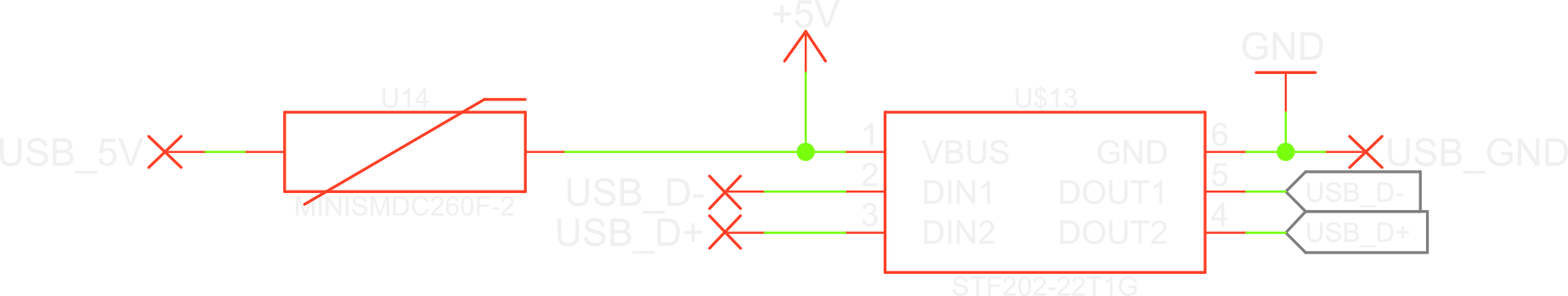
I did a bit of reading, most notably this document. Apparently you want to constrain the voltages on both the power and data lines using Zener diodes, in case of overvoltage events. TVS-diodes are used to protect against ESD. Polyfuses (resettable fuses) are then needed to constrain the current to the above parts.
What happens, is that in an overvoltage event or an ESD shock, some high voltage is applied to the diodes. This voltage will be higher than their breakdown voltage, so they will start to conduct current, even though they’re reverse biased. Since a low impedance path has now formed, all the current will flow to the diodes, rather than through the protected device. All this current would cause the diodes to blow up, so we place a fuse on the way to the diodes. That way, when the current starts flowing, the fuse trips, and the device is protected. However, it would be annoying to have to replace the fuse every time you accidentally zapped your device. Because of that, we use a resettable fuse. This is basically a resistor with a really high positive temperature coefficient. As soon as a large current starts flowing, it heats up, and because of that its resistance increases, which causes it to warm up even more. This cycle continues until almost no current flows through the part anymore.
Luckily for us, parts are sold that have almost all input protection built in. The only external part we need is a polyfuse for the power line. I used the STF202-22T1G for input protection, coupled with the miniSMDC260F-2 polyfuse:
Auto switching power supply
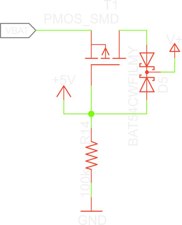
This project needs to be able to be used without external power, so it has an internal battery. The tricky thing is: you can’t draw current from the battery while it is charging, and you do wan the device to be usable while charging.
The reason you can’t draw current from the battery while it’s charging, is because it would trip up the battery charging circuitry. It monitors the current going to the battery, and when you start drawing current from it, it detects a sudden rise in charging current. This may make it shutdown, or supply less current to the battery, which would increase charging times.
To solve this, we need to switch between internal and external power intelligently. You want a circuit that is as efficient as possible, and disrupts the power while switching as little as possible. I looked for existing solution on the internet, and eventually found something that strikes my fancy on the electronics stackexchange. It is explained pretty well there, so I won’t repeat it here.
So those are most of the details on the electronics design, except for the capturing of the delays between the ultrasound signals. This is quite complicated, and I think it deserves its own post. I will post that next time.
Discussions
Become a Hackaday.io Member
Create an account to leave a comment. Already have an account? Log In.