 Rajendra Bhatt
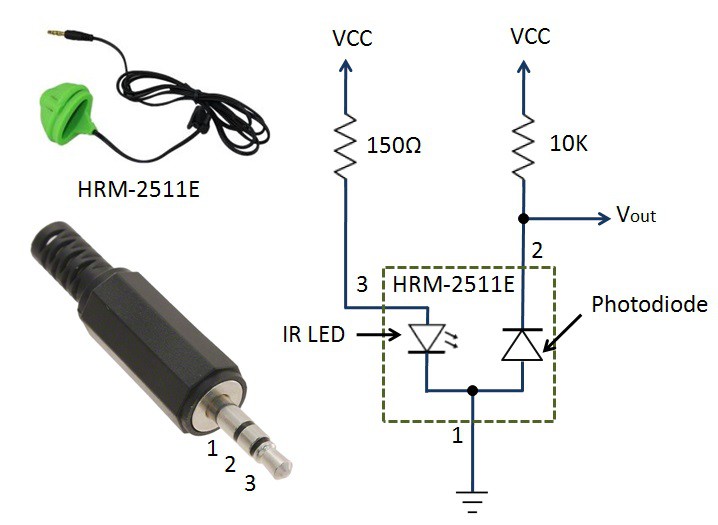
The following figure shows a basic DC biasing required for the HRM-2511E sensor. The sensor has three pins that are wired to a 3.5mm stereo audio connector. A 150 Ohm resistor is placed between VCC and the anode of the IR-LED to limit the current through the IR LED. Similarly, a 10K resistor provides a DC bias to the photodiode. The raw PPG output (Vout) from the photodiode is a very weak and noisy signal that swings about this DC bias voltage.
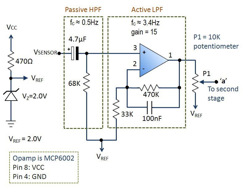
The photodetector output is passed through a 2-stage non-inverting instrumentation circuit built with Microchip's MCP6002 dual OpAmp chip. The two instrumentation stages are identical and have a maximum gain of 15 per stage (total 2-stage gain of 225). The negative input of the OpAmp is tied to a 2.0V reference voltage derived using a zener diode. This prevents the clipping of the negative swing of the PPG signal at the output. The instrumentation circuit is further divided into two parts: a passive RC high-pass filter (HPF) with a cut-off frequency of ~0.5Hz and an active low-pass filter (LPF) with a gain of 15 and a cut-off frequency of 3.4Hz. This constitutes a band-pass filter (BPF), which allows signals with frequencies between 0.5HZ and 3.4Hz. Therefore, it filters out the DC bias signal (which is 0Hz) in the photodetector output, as well as any high frequency noises (such as mains 60Hz frequency) present in the PPG signal. A 10K potentiometer at the output controls the amplitude of the output signal that is fed to the next stage of instrumentation.
The second stage (shown below) consists of the similar passive high-pass and active low-pass filters. The output of the second stage has sufficient dynamic range and can be directly fed to an analog input channel of Arduino or any other microcontrollers.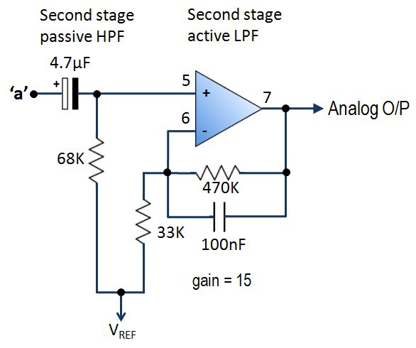
Discussions
Become a Hackaday.io Member
Create an account to leave a comment. Already have an account? Log In.