 RoGeorge
Yesterday I was building a headphone amplifier, and was looking for a differential voltage source. Something small, preferable a wall adapter. Any fix voltage in the interval +/-5V ... +/-15V would be just fine. Expected current 100...150 mA.
Most wall adapters from the scrap box were from old mobile phones, single voltage, 5V or less, with glued cases and no way to adjust the voltage. Still, there was one with a screw-fastened case, single voltage, 8.4V/500mA:
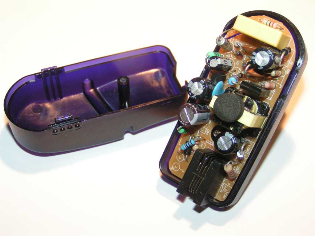 It has a 4 wires RJ9 female connector (like a LAN connector, but with 4 pins only), which was perfect, because I needed at least 3 wires, but preferably 4. Even more, the schematic was very hacker friendly:

All it needs to add a negative voltage was another rectifier circuit, like the one in red: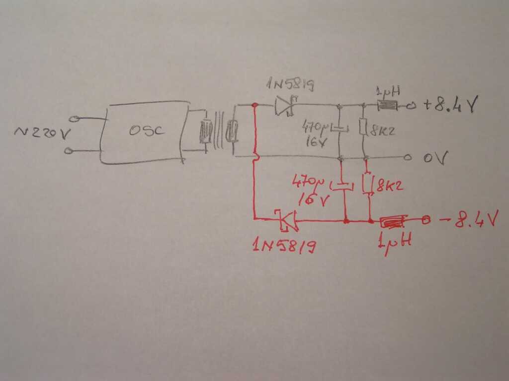
Even more, the PCB had an un-populated area in the lower voltage part, more then enough to add the 4 red components.
That was too nice to be true!
When something is too nice to be true, most of the time it's because it's not!
After the red part was added and everything was double checked, it was time to plug it in.
Does it worked? No.
Instead of +8.4 / -8.4V, the output was +8.4 / -25.2V. Exactly 3 times more negative voltage then expected.
Can you spot the mistake?

I assumed for a symmetric oscillator, but look at the waveform.
It was not symmetric at all, which is normal for a SMPS charger with a simple oscillator.
The waveform was measured after the facts, just to confirm the reason of the failure.
:o)
Discussions
Become a Hackaday.io Member
Create an account to leave a comment. Already have an account? Log In.
You still stand a chance! Perhaps you will be lucky enough to find the secondary winding is the last one wound on the easily disassembled EI transformer. In which case you can unwind it (keeping the # of turns in mind) and wind it again in a bifilar fashion, with the common point being ground and ends to connect to two symmetrical rectifiers/filters. Of course assuming you could be bothered to tinker a bit more with the little bugger ;) Good luck anyway!
BTW - The waveform you obtained seems pretty expected for an el-cheapo flyback SMPS.
Are you sure? yes | no
Good idea, thanks!
In the meantime I changed my mind about using a cheap & old (read unsecure) 220V powered charger for something that will end up with a couple of wires around my head. Also, powering it from batteries will not only be more safe against dumb self-electrocution, but also more safe for any expensive headphones that might be connected to the amplifier, and more "audiophile grade" because batteries have zero power hum.
Are you sure? yes | no
My personal favourite would be an 18650 cell feeding a pair of DC/DC converters - one "boost", the other "inverting boost".The batteries aren't inherently low noise either - look here: http://www.tnt-audio.com/clinica/regulators_noise4_e.html - but armed with that Rigol you can weed out any PS noise :)
Are you sure? yes | no
Hah! This is a new form of SMPS-design for me, I'da never expected! Throw in a -9V regulator and maybe you can turn that fail to a win!
Are you sure? yes | no
Good idea, but for the moment I won't bother with it any more, so I will just call it a +8/-24V win! :o)
(thought, I bothered changing the 470uF/16V, which miraculously didn't explode in the first minute, with a 470uF/25V)
"Life is like a box of chocolates, you never know when you're gonna need a +8/-24V!"
Are you sure? yes | no
Old LCD displays need just about exactly that :)
Only thing, though... I'm not sure that as the 8V load increases, that -24V may drop down...(?)
Are you sure? yes | no