Main problem I have with this stop-watch is its photo-barrier range. At dark, everything seems to be all right, the IR emitter can be as far as 5m (15ft) away, but when I'm outside, and the weather is sunny, range decreases dramatically down to 2m (6ft) or less. This is probably due to the fact that sun emits full spectrum of very intense visible and IR light, and fools the receiver. It simply cannot distinguish IR pulses from the emitter from background IR light, even though emitter modulates the signal, and sun does not. To overcome this, I must assure, that the emitter does its best, and the pulses are strong, and exactly 38kHz, and receiver is not exposed to direct sunlight. Probably some form of lens hood on the receiver would do the job, but lets focus on the electronic portion for now. The simplest circuit I tried was this (two 4047 multivibrators are not shown, I use them to generate the signal which would be attached to R1 instead of V2):
![]()
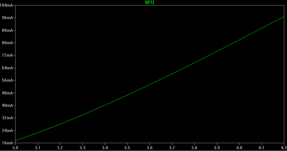
D1 is a TSAL6200 IR diode from Vishay, and can handle up to 100mA pulses, so this circuit simulates 100mA through the D1 when V2 equals 4.2V which is the max voltage a LiPo cell can provide (when fully charged). But what would happen when battery runs out to, lets say, 3.4V which is (I believe) the lowest acceptable voltage a LiPo battery can work with. LTSpiceIV (which is excellent, and runs under wine flawlessly) shows that current through the IR diode drops significantly (approx. 40mA when V2 equals to 3.4V and not much more than 55mA when battery provides 3.7V which is fairly typical for a LiPo):
![D1 current]()
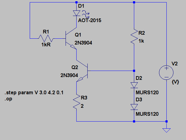
To prevent that, I figured out, that I should use a current source. So I came up with the following circuit:
![]()
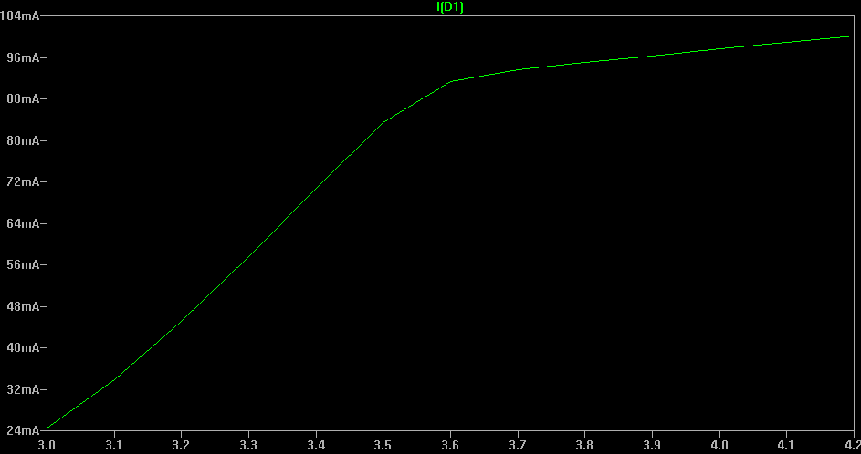
Q2 and R3 works as a transistor current source which forces approx. 100mA through the D1 and Q1. R2 and two serially connected diodes are for biasing Q2. They provide approx 1V to the base of Q2. Q1 at the other hand works as a simple switch, which again would be connected through R1 to the 38kHZ 1ms bursts source. It can instantly turn on and off all this 100mA current which lights up the D1 diode. Again LTSpice shows what would happen with D1 current when V2 voltage source runs out (from 4.2V to 3.0V):
![Current through the IR diode D1]()
Looks better, but real life tests should be performed.
 lukasz.iwaszkiewicz
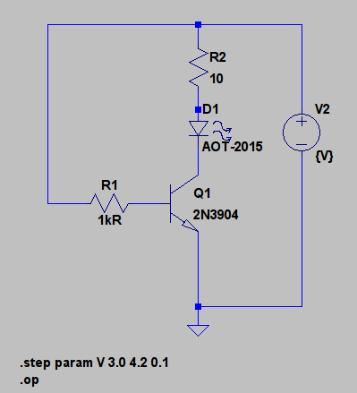
Discussions
Become a Hackaday.io Member
Create an account to leave a comment. Already have an account? Log In.