 Andrew Starr
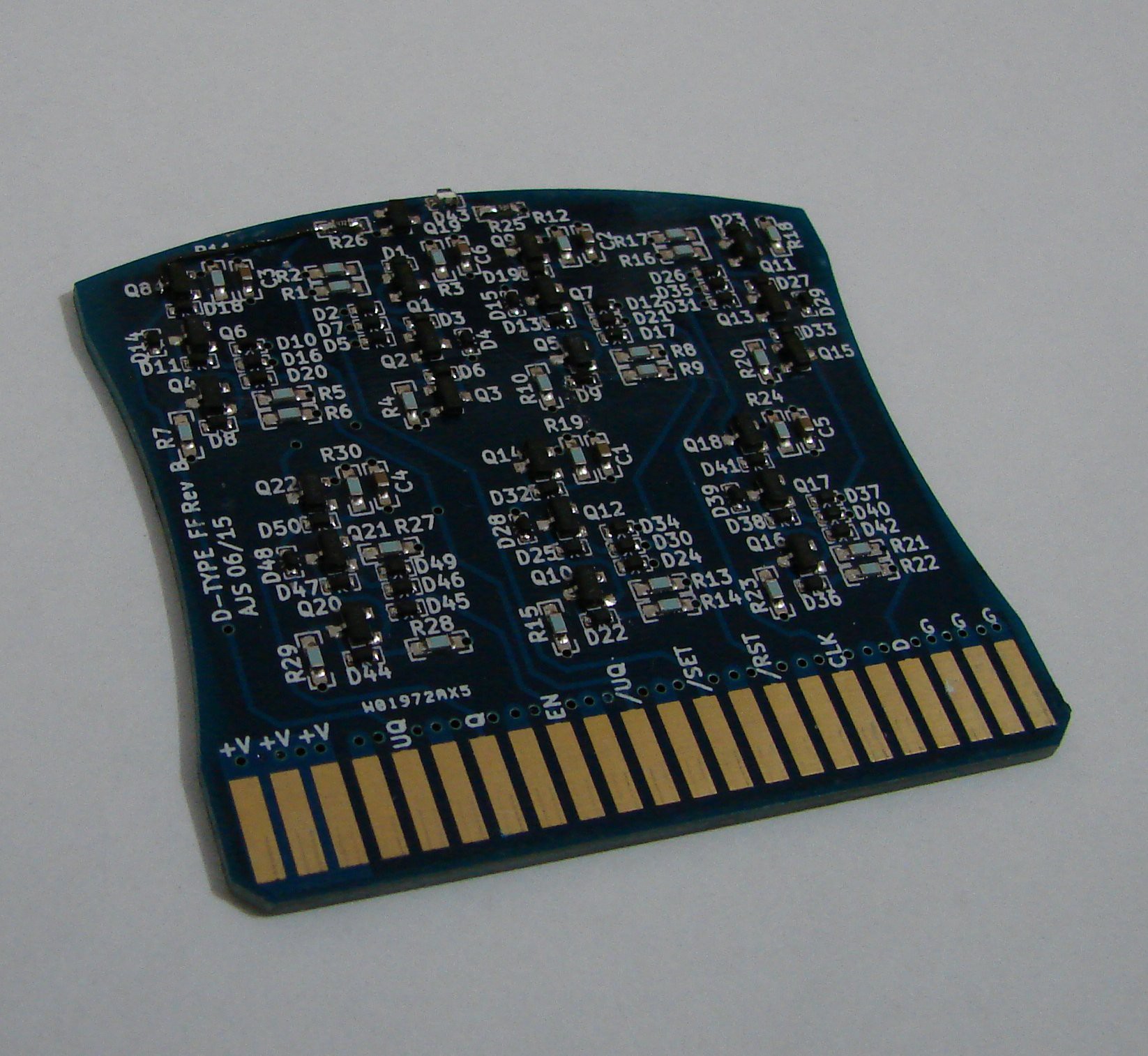
The first in a series of logic modules has been completed: a D-type flip flop with asynchronous SET and CLEAR, and tristateable output. It is a 6 NAND-gate arrangement similar to the 74S74. The PCB is 4 layers, and the transistors are MMBT3904s with BAT54 Baker clamps.
I've simulated it with LTSpice and it should be capable of a least a couple of MHz.
This is Rev B. Rev A worked, but I decided to make the module sides slightly concave to assist insertion and removal, and to curve the top - I think it looks nicer. I also decided to go for an edge connector - the 44-pin Multibus II.
And yes, that is a kludge wire near the top!
 Here are 18 waiting to be tested:
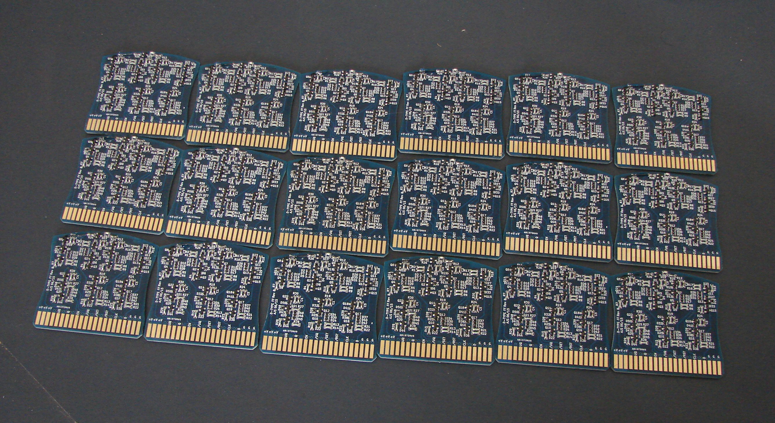
The PCBs were made by pcbway.com. I had a kapton stencil made by OSH Stencils. I did the reflow soldering in an old toaster oven controlled by a Zallus Oven Controller.
Now I need to build a jig to test them!
Discussions
Become a Hackaday.io Member
Create an account to leave a comment. Already have an account? Log In.
You are vintage or you are not ;-)
Are you sure? yes | no
I think I'll save the Freon cooling for the T-2 :)
Are you sure? yes | no
Actually now that I think about it, active cooling isn't all that retro, what with every script kiddie's overclocked PC having some kind of water cooling or whatever.
The T-1 will be air-cooled, like a classic motorcycle :)
Are you sure? yes | no
Or you can think in reverse and say "look at my fancy blinky heater" ;-)
Are you sure? yes | no
I've hooked 4 up as a ring counter, and driven them up to 2MHz, which is as high as my signal generator goes. I've found LTSpice to be reasonably accurate so far (although I haven't asked too much of it as yet). It will be interesting to see how accurate the simulations of the core rope ROM turn out to be.
And yes, power consumption is the killer :) It was fun fiddling with resistor values in the simulator and seeing the effect of power vs. speed.
10MHz? Wow, that's pretty cool! And that's with a resistor pullup instead of a totem-pole output? I'm wondering if I've overengineered my gates :) My NAND gates have an input NPN driving a totem pole output. The input transistor has a base pullup and 2 BAT54s as the gate inputs. All 3 transistors have BAT54 Baker clamps.
Ultimately I'm expecting the ferrite core RAM to be the bottleneck. I'd be happy to get 1us switching times out of the cores but this might be optimistic.
Are you sure? yes | no
After a lot of real world testing different configurations I'm currently satisfied with using standard diodes in the NAND inputs with a 330 ohm pullup there. Two standard diodes in series with the base as a level shifter with a 470p cap across them for speedup. No Baker clamp. A 680 resistor from base to ground. The output pullup is between 180 and 270 ohms depending on the load.
I use bc847 for internal nodes and 2n2222 and the 180 ohm pullup for drivers.
I've tried replacing the input diodes with PN junctions of transistors, but got no real gain there. A baker clamp gives about the same speedup as the 680 base pulldown, and a resistor is cheaper and (smaller unless using an evil MELF) than a BAT.
And yes... I run it on about 2.5 volts. That gives a about 30% speedup compared to 3.3.
Are you sure? yes | no
The BAT54s I'm using are SOD-523s...smaller than 0603 resistors, and hard to tell apart from random bits of crud on the bench :)
I think in terms of numbers of discretes we come out about even, except I'm using a couple more transistors, just to avoid having to sink the pullup current when output is low. But then the name of this game is tradeoffs!
I picked 3.3V as a 'safe' voltage to use as I will be using a lot of blue LEDs (blinkenlights) and by the time you add up the forward voltage drop + Vce of the transistor switching it you're looking at something approaching 2.5V. But we'll see - no harm in winding the voltage down until things stop working, then back up a bit :)
Are you sure? yes | no
Have you tested the speed yet? I've discovered in my project that the LTspice simulations and the real world speeds differs an order of magnitude... But I've reached close to 10 MHz for my fllipflops at the expense of a horrendous power consumption.
Are you sure? yes | no
Some guys reached 30MHz in the 60' ;-)
http://ygdes.com/CDC/cdc6600.html
Are you sure? yes | no
I'm hoping to avoid having a refrigeration unit on the T-1 :)
Are you sure? yes | no