 The Big One
We spent most of the weekend manufacturing the femur part of the legs + the new chassis, along with the coxa joints (where the legs meet the chassis). This post includes documentation on how this was done. (I apologize about the quality of the pictures... I didn't want the bother of bringing out my real macro setup, so just used my camera instead. Hopefully it at least shows what was done...)
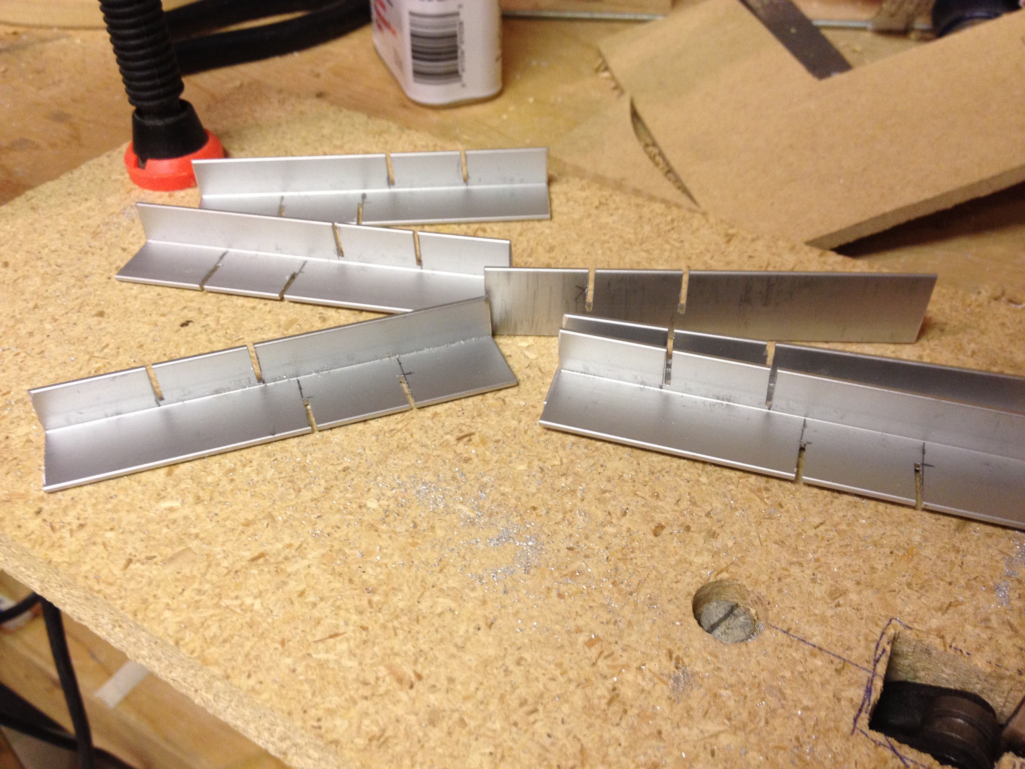
1) The femurs were cut to length (100mm) from the aluminum L bar stock, and the edges of the servo indentations were cut. (Pro tip: Triple check that you are cutting the right side!!! Keep in mind that for symmetry reasons, half of the legs are mirrored from the other ones). We used an upside-down mounted jig saw with a metal blade for this:
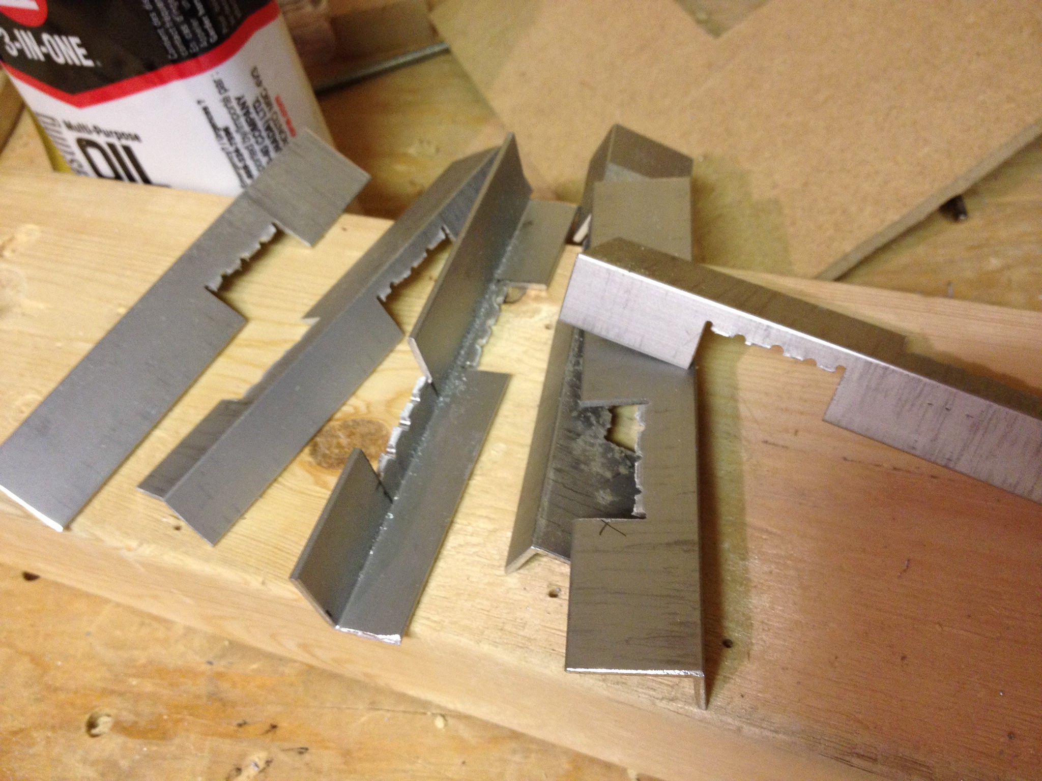
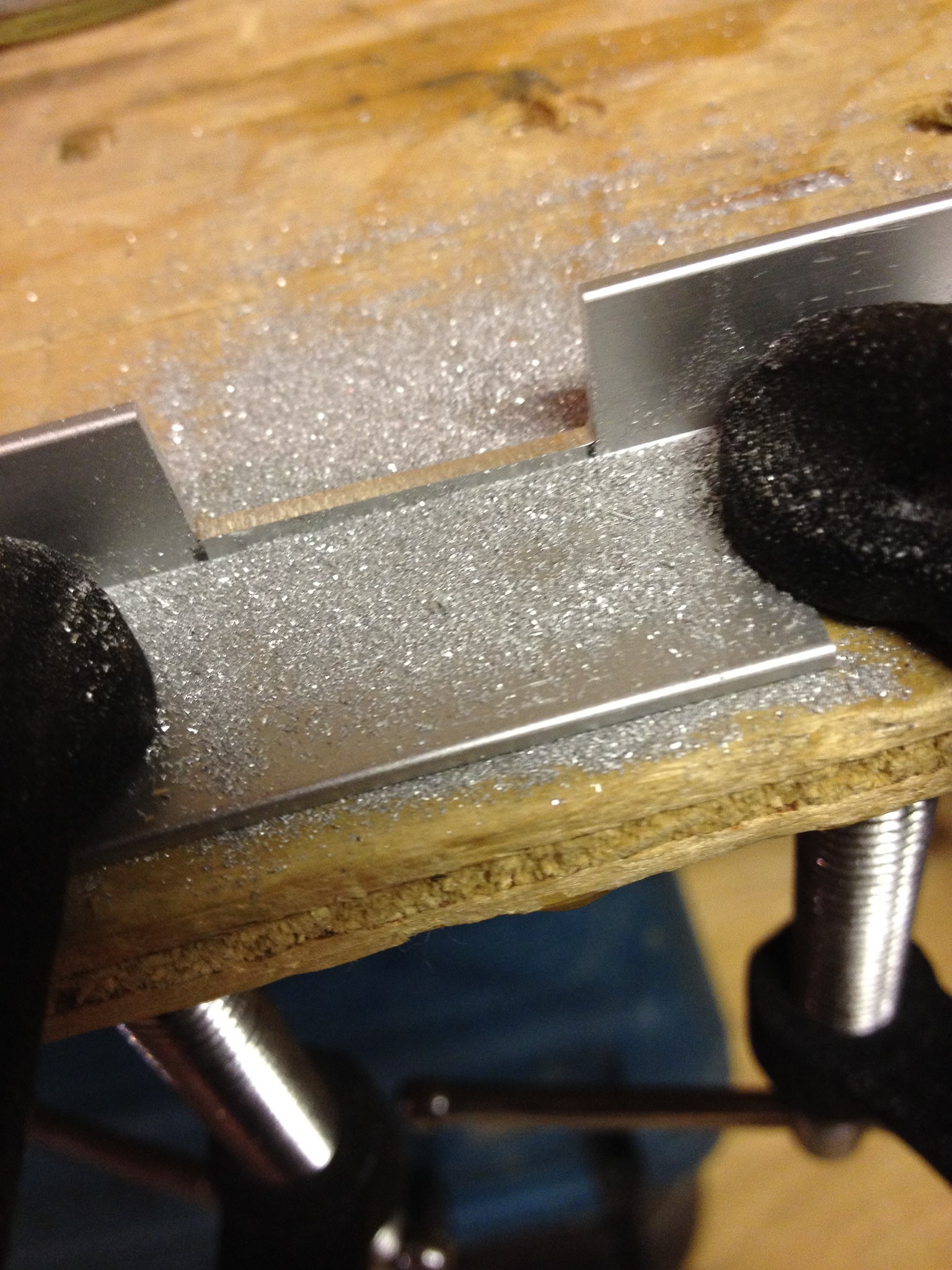
2) Relief holes were drilled into the bottom of each servo indent (I don't know how else to cut this sort of shape into aluminum bar given the tools at my disposal).
3) The sections for the servos were snapped out. With the relief cuts this is easy; just bend it about 10 degrees with a couple of pliers and move back and forth.
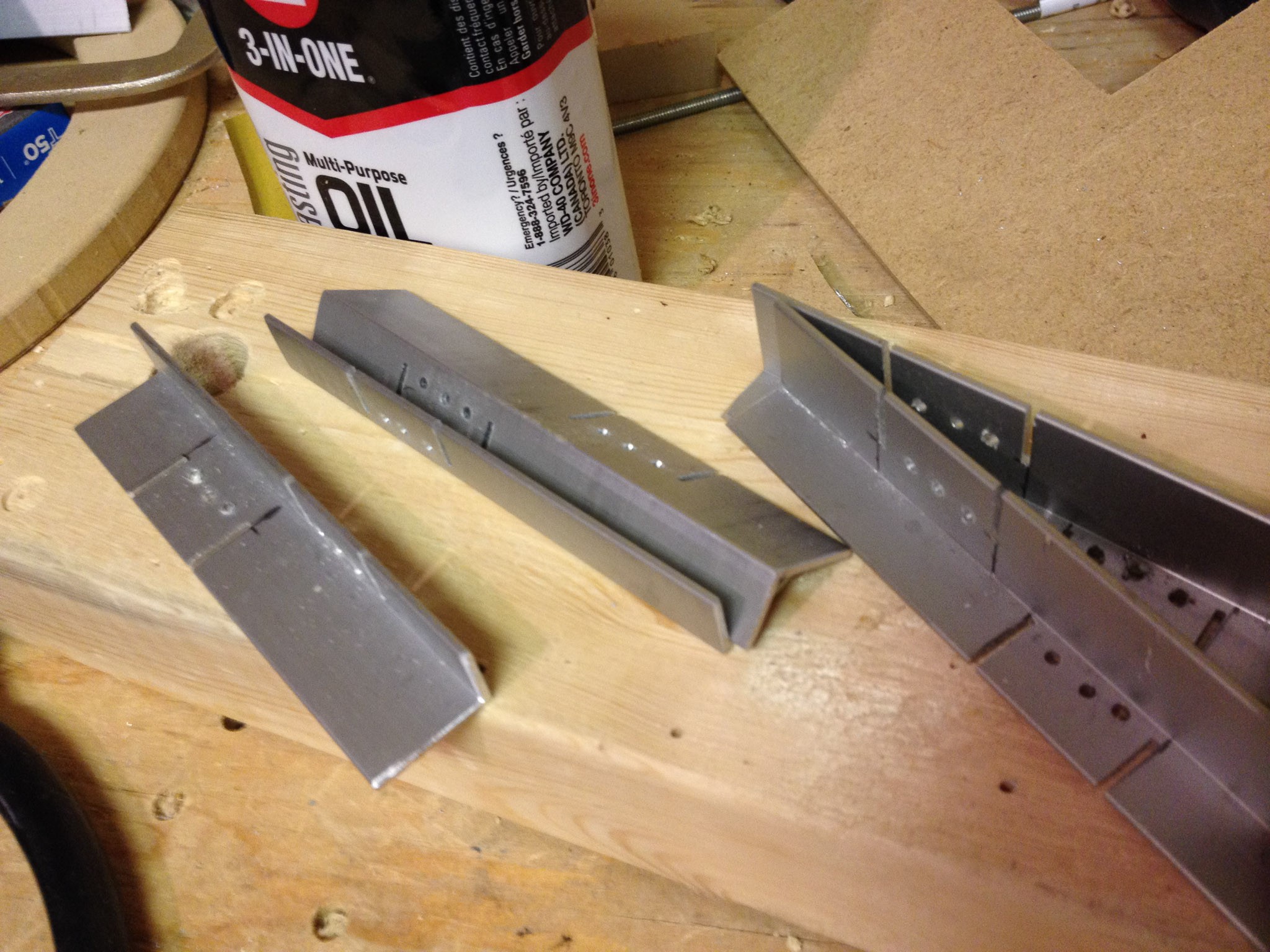
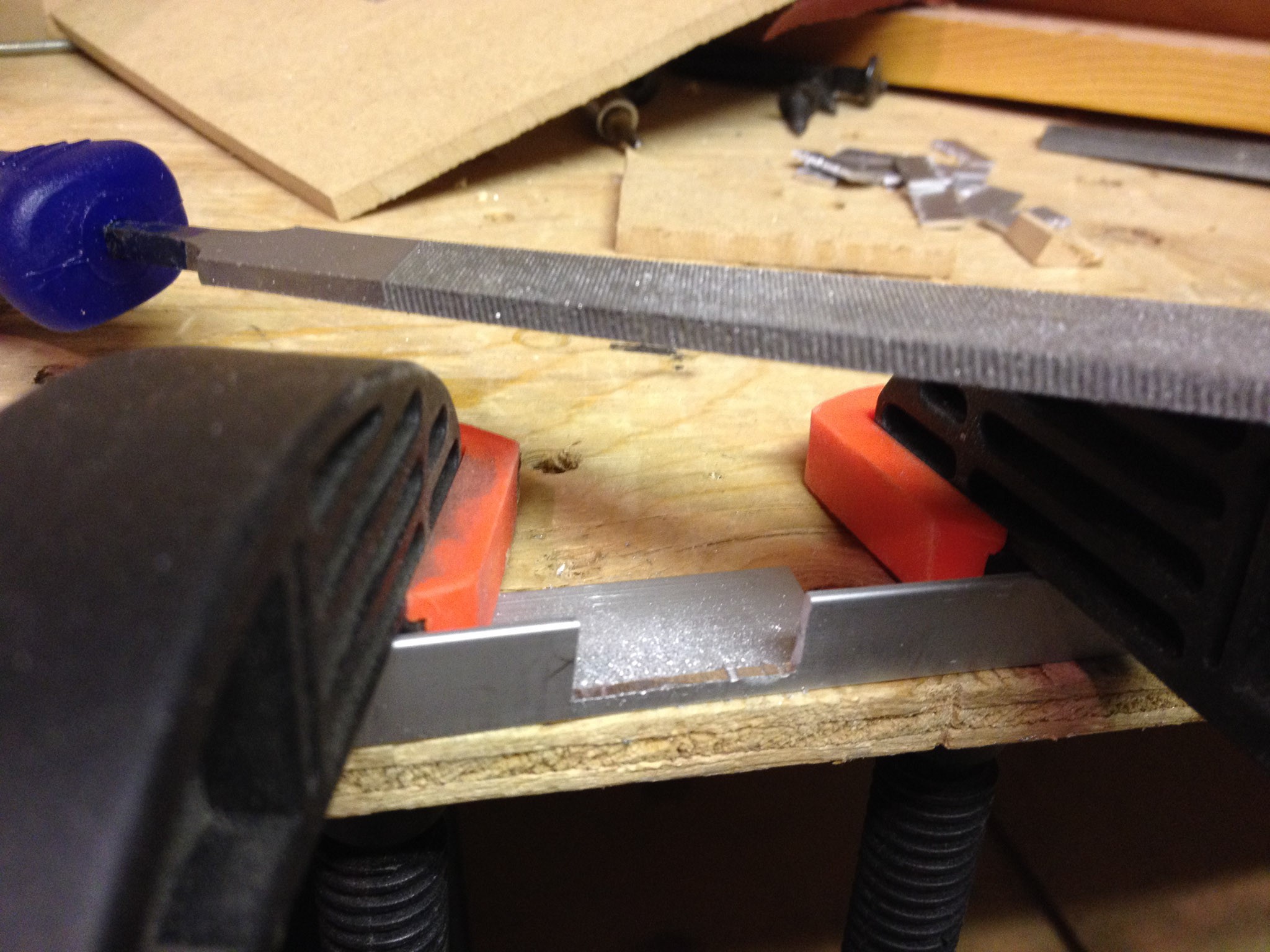
4) Using clamps and a flat file, smooth the jagged bottom of the servo holes, and slightly enlarge the sides to fit the servos, measuring each hole as you go.
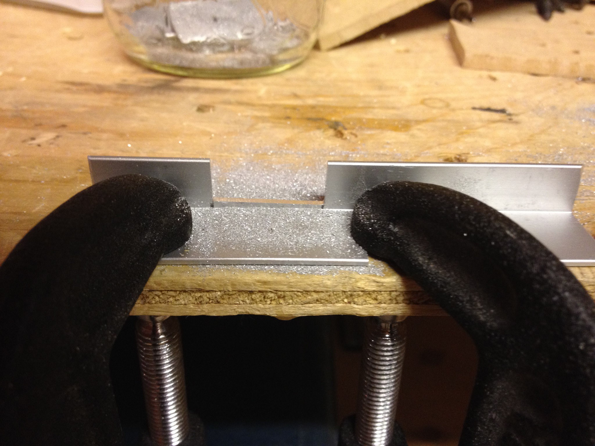
5) Measure, and drill the servo mounting holes.
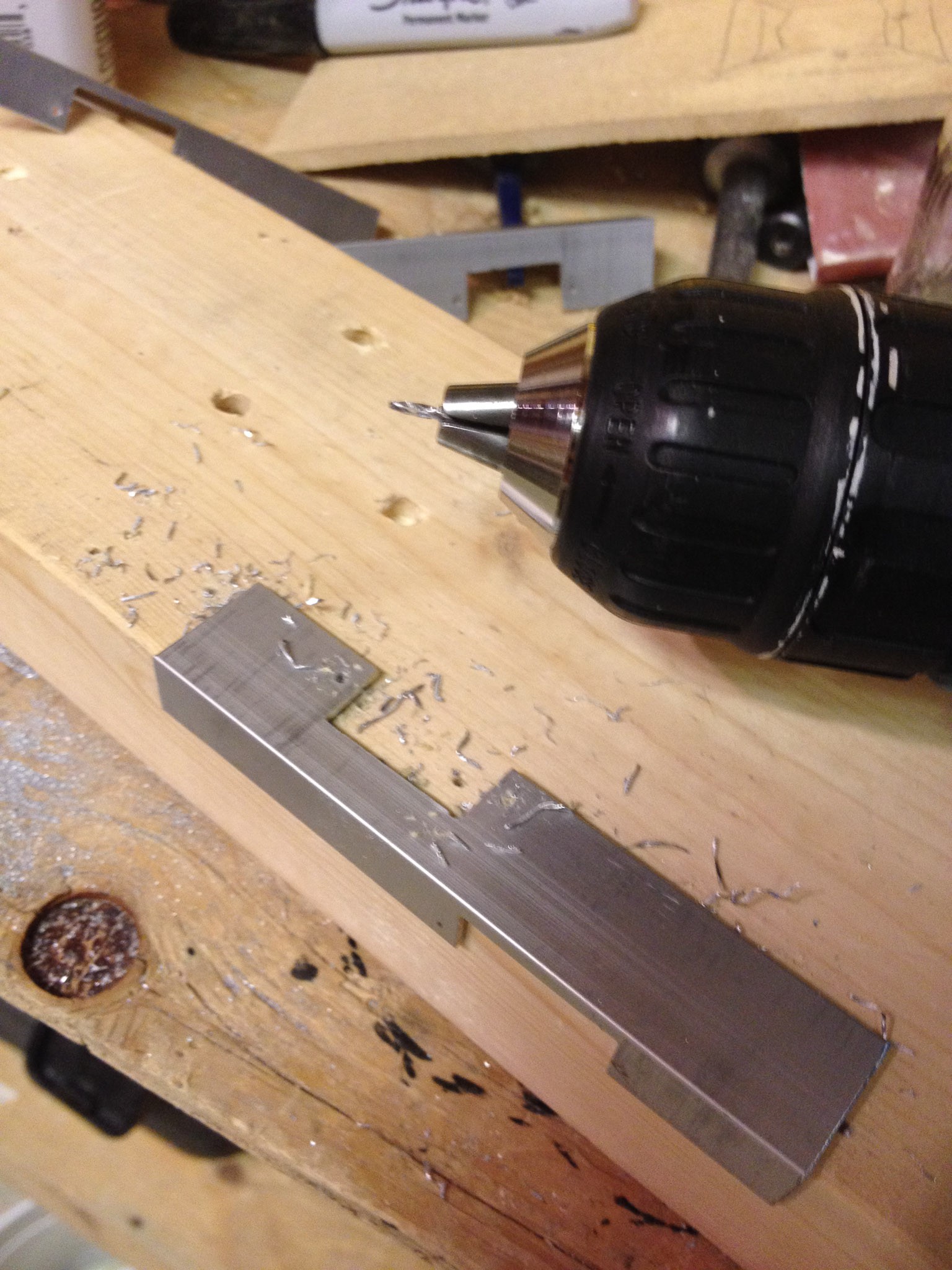
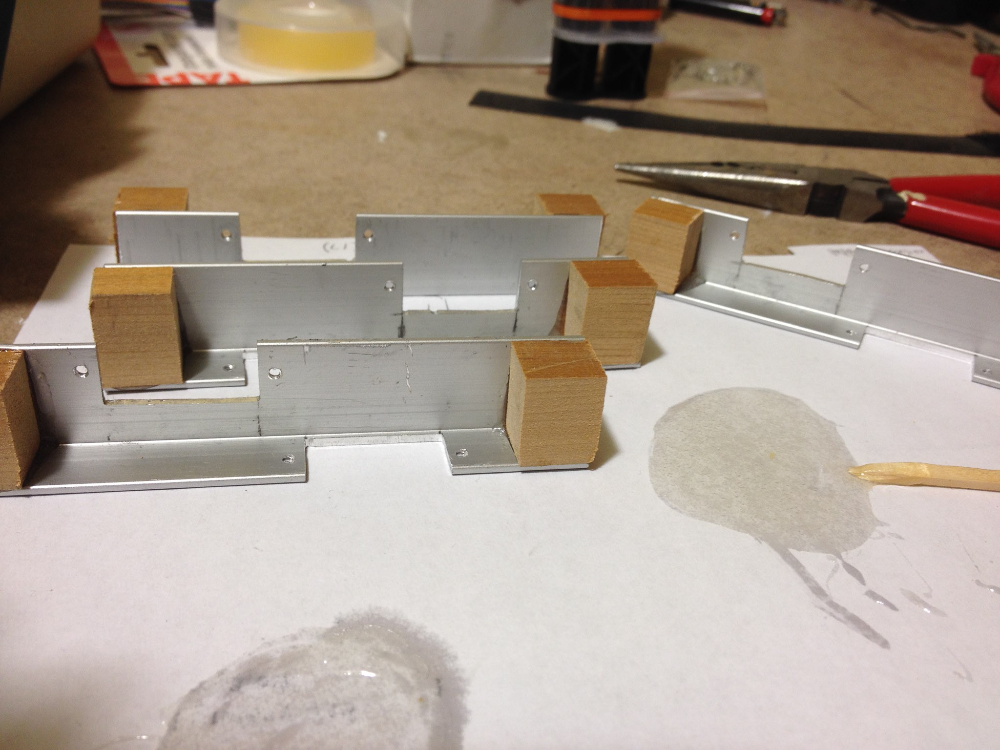
6) Cut the wooden backing pieces to size. I just used some scrap 3/4" cedar I had lying around (removed from my bathroom renovations a few years back), but any sort of wood should be fine here. Hard wood (oak, maple, etc) would probably work best, but I didn't have anything around.
7) Using a high strength wood / metal epoxy, glue each piece into the aluminum brackets.
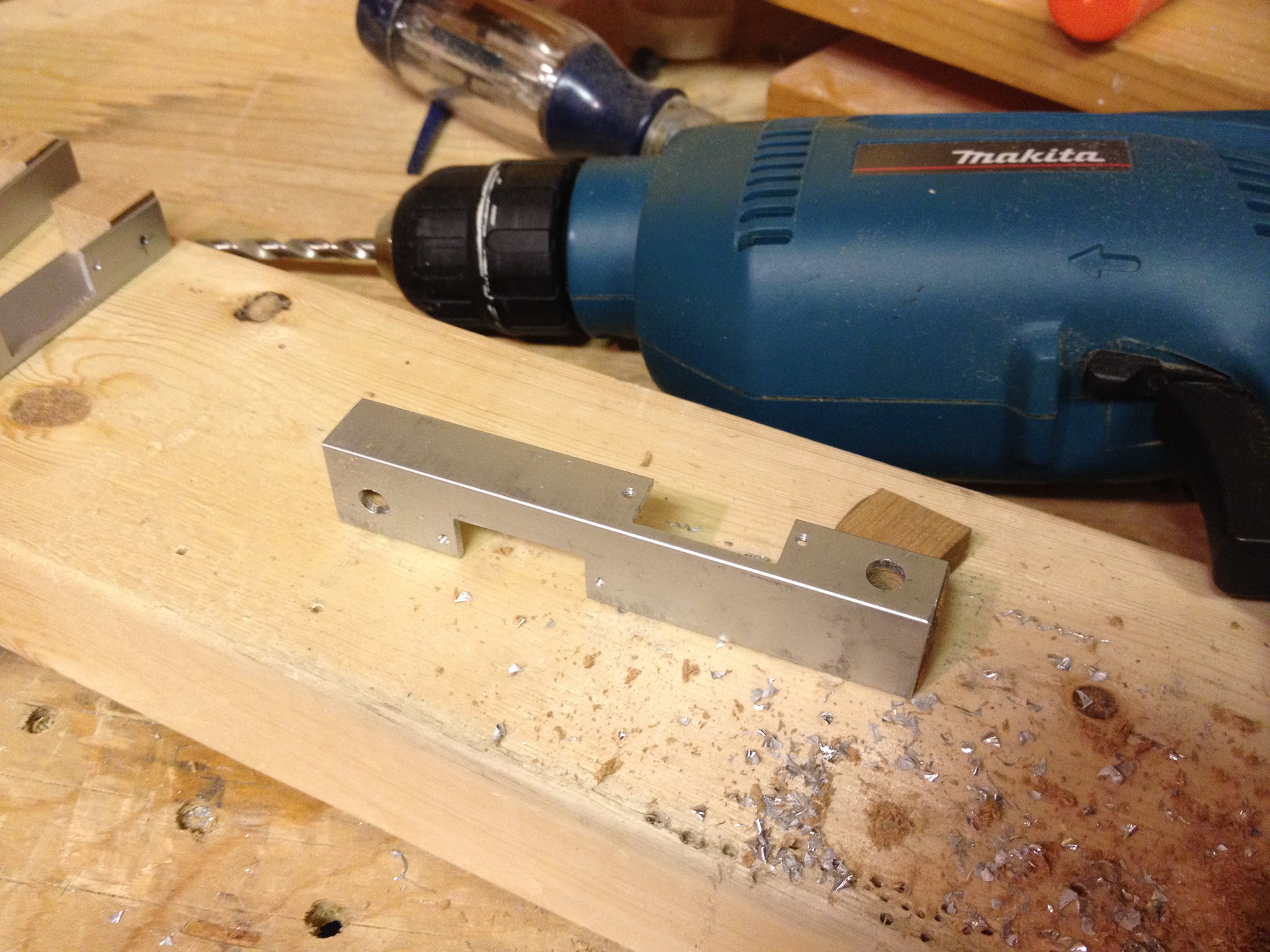
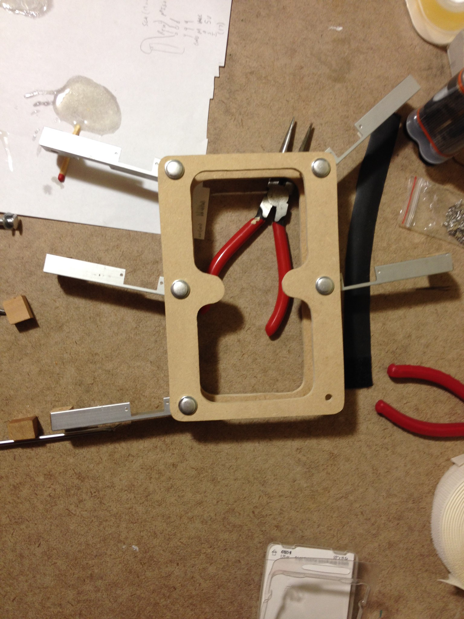
8) Drill the joint holes through the metal + wood. A drill press would be best for this, but unfortunately I don't have one. A pilot hole definitely helps here. Pro tip: X marks the spot before drilling, do this on both sides of the piece. When you drill the pilot hole, drill from the aluminum into the wood, and verify that the exit hole is on the X marked on the wood side. Then, when drilling the full sized hole, drill from the wood to the aluminum, then stop and flip the piece and drill from the aluminum to the wood. (I managed to split one of the pieces when I just tried to drill straight through from aluminum to wood). Putting the piece in a vice or clamp would probably help to prevent splitting here, too.
9) Cut out the chassis pieces and drill. I used my upside down jigsaw for the outer cuts + rough inside cuts, and then a dremel-mounted drum sander for the inside edges. I unfortunately do not have any pictures of this process.
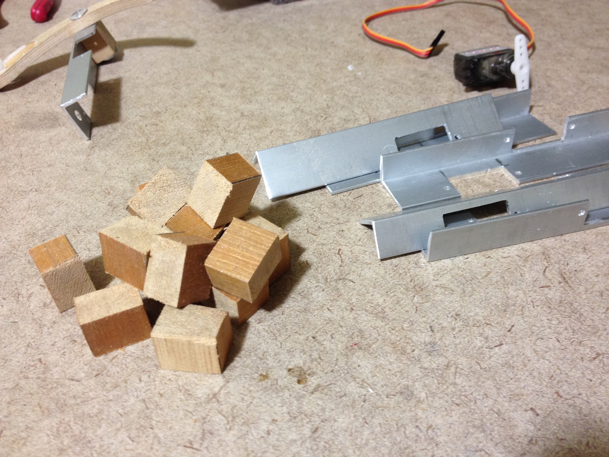
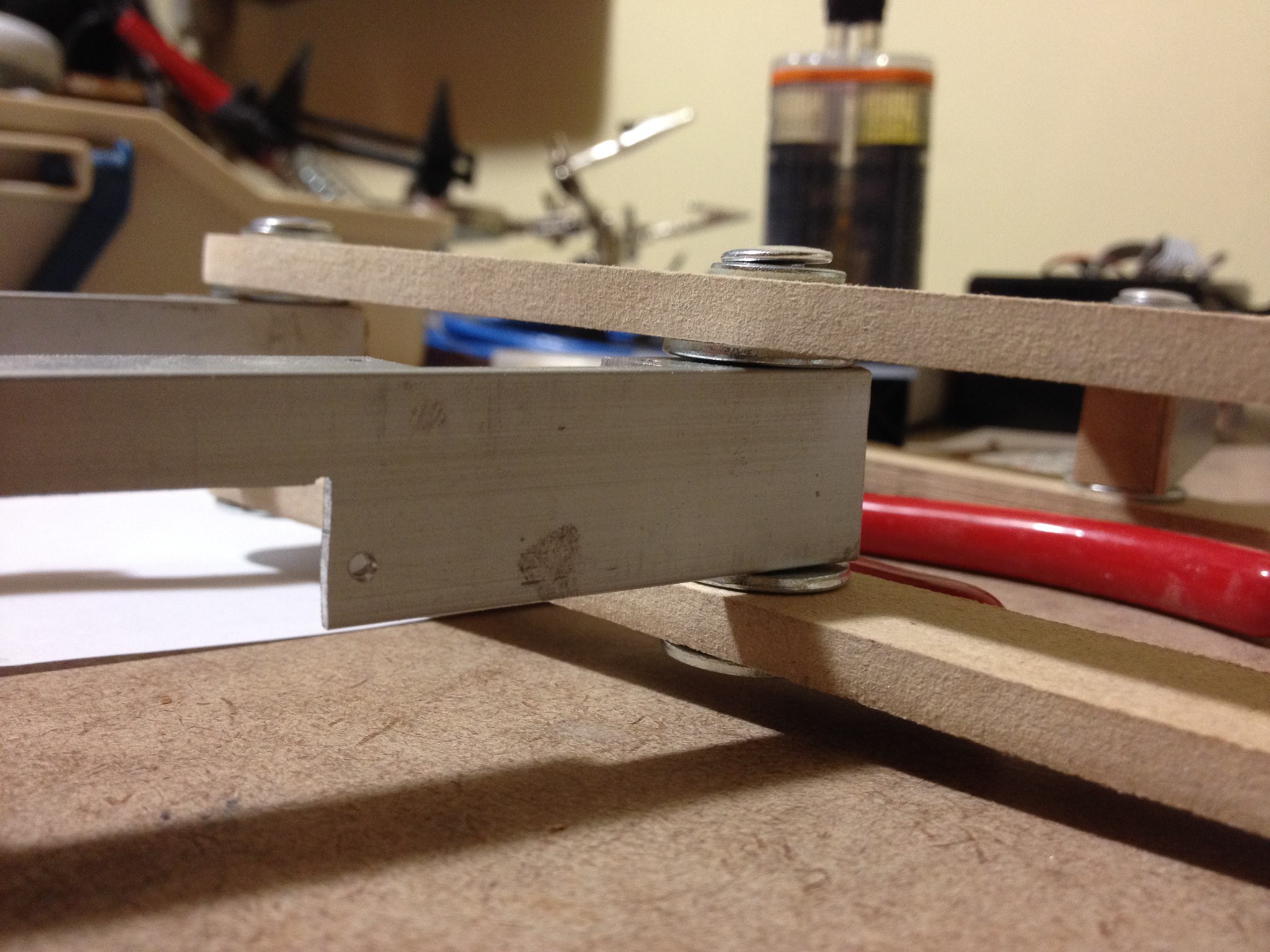
10) Mount the legs into the chassis. We used 1" Chicago bolts for the axle, separated by washers between each layer. The legs should rotate freely.
11) Mount the coxa servos. This is pretty simple... we put the motor end on the outside of the leg but this is somewhat arbitrary. No pictures here...
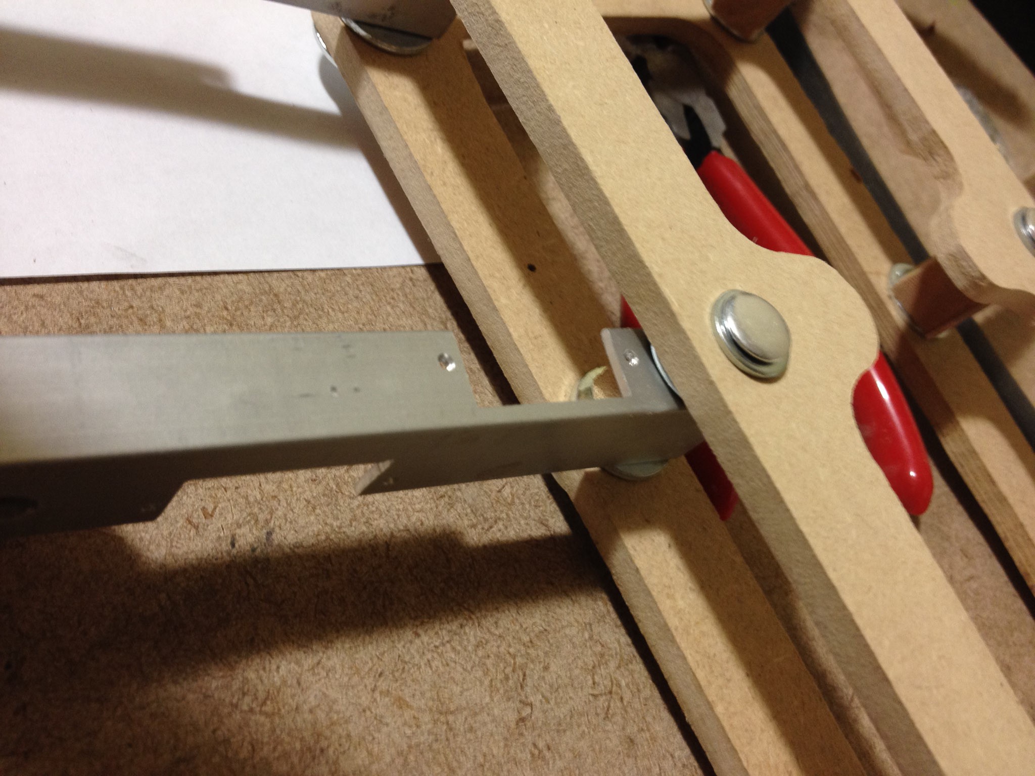
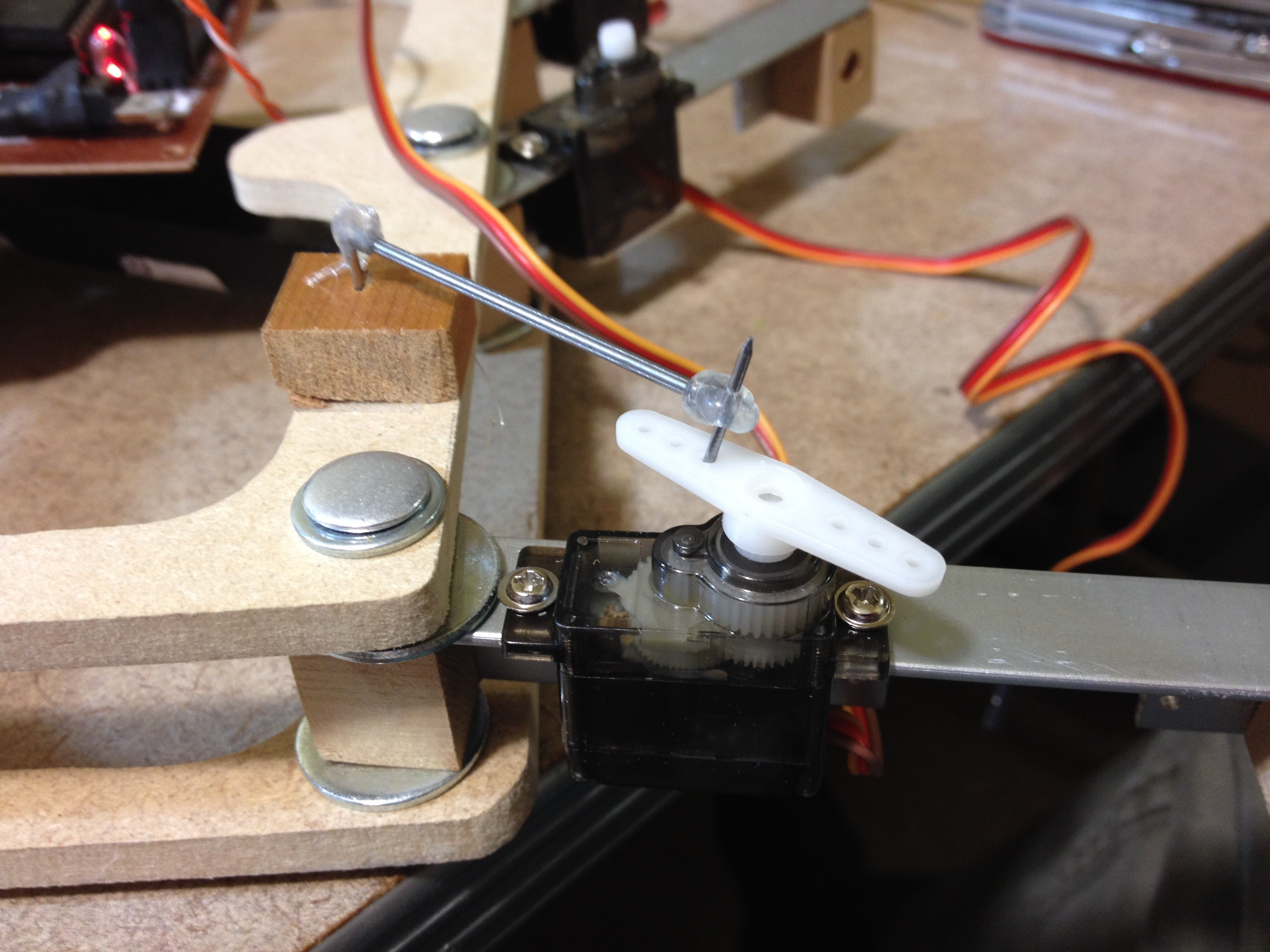
12) Hacking on a rough-and-tumble proof of concept of the drive rods using nails and hot glue (a.k.a. the poor man's 3D printer). It works beautifully! Adjusting how close the chassis side of the mount (the wood block with a nail in it) is to the coxa joint determines how much travel the leg has. I want to keep the leg travel to about 30 degrees total (15 in front and 15 behind neutral), so when adjusting the mechanism I will be keeping that in mind.
For a video of this in action, see Youtube.
What's next?
Next up is designing the final push rod. I have a few ideas that I am mulling over in my head... I want to use a threaded rod so that I can make fine adjustments to the angle of the legs. I will post more on that once I have a prototype ready.
Enjoy!
Discussions
Become a Hackaday.io Member
Create an account to leave a comment. Already have an account? Log In.