The Big One
-
No News is Good News
08/18/2014 at 02:11 • 0 commentsI have not done any project updates for a while here... first, and most importantly, we have been on vacation most weekends, camping all over the place:
![]()
Secondly, I am still waiting for a bluetooth module for my PC which I had ordered on eBay. (I had ordered one a few months back, but after it came I discovered that it was incompatible with Linux... the one I am waiting for now is advertised as being Linux compatible, so here's to hoping).
I expect that this project's progress will get back on track in September.
Cheers
-
Computer Control Verified and Working
07/28/2014 at 21:43 • 0 commentsAfter a number of very busy days where I was unable to work on Stubby at all, I have finally found enough time to hook up the Bluetooth radio and verify that everything works. So far, I only am emulating the Universal Controller's protocol (which, BTW, works very well; I may actually write up a simple computer-based controller which lets you use a keyboard to control it rather than relying on a separate physical controller).
The proof of concept code is below: simply put, it turns Stubby on (hits the "Start" PS2 button), moves forward for one second, backwards for one second, stops for a second, and then turns Stubby off again.
#!/usr/bin/env python2.6 # # Simple POC for computer controlled Stubby movement # ################### import serial, sys from time import sleep ser = serial.Serial("/dev/tty.Stubby-DevB", 38400) ser.write("\x93") #Start (to begin) #Reset all analog controls (not strictly needed) ser.write("\x0F") #Left X to neutral ser.write("\x2F") #Left Y to neutral ser.write("\x4F") #Right X to neutral ser.write("\x6F") #Right Y to neutral sleep(0.01) #Movement ser.write("\x20") #Forward ser.write("\x10") #Left X to neutral sleep(1) ser.write("\x3F") #Backward ser.write("\x10") #Left X to neutral sleep(1) #Stop ser.write("\x0F") #Left X to neutral ser.write("\x2F") #Left Y to neutral sleep(1) ser.write("\x93") #Start (to end) -
3D Printer Files
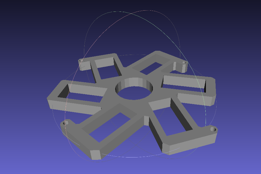
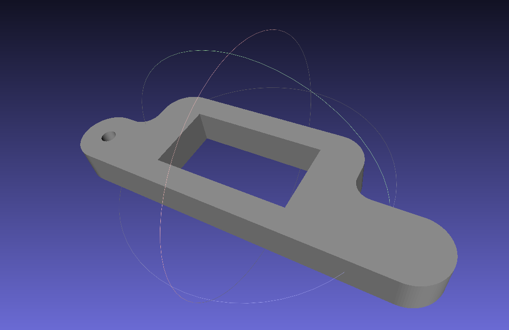
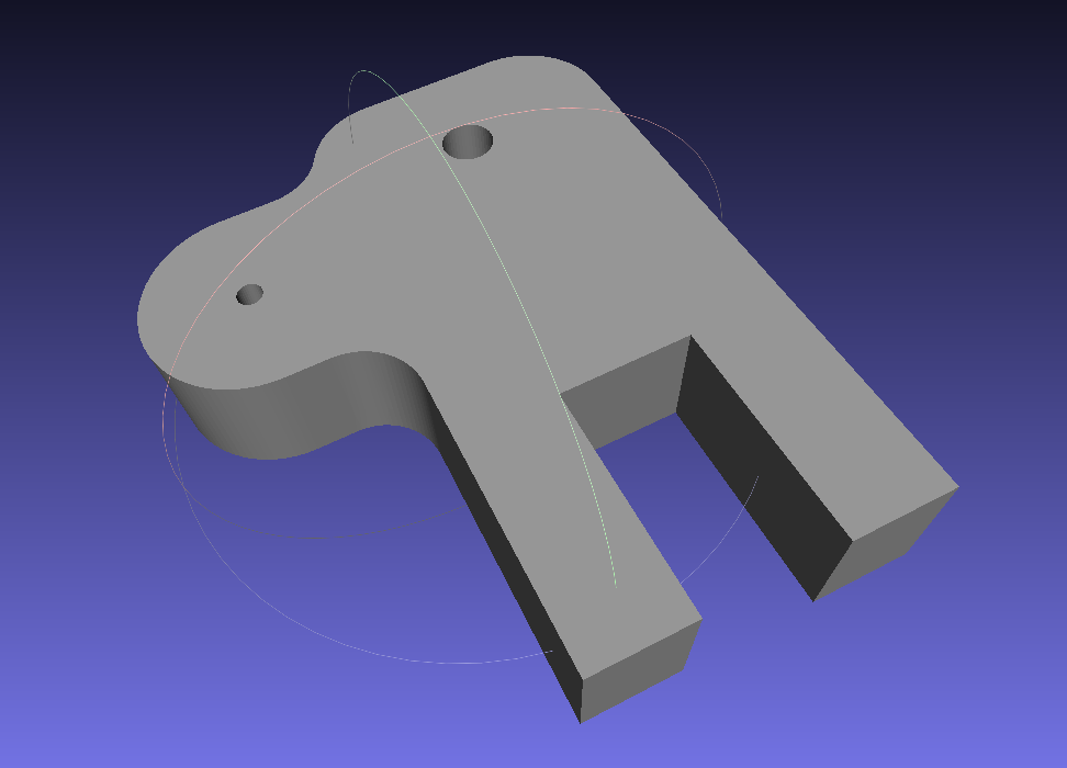
07/28/2014 at 15:14 • 0 commentsThanks to Joshua Thompson, there are now 3D printer source files for Stubby's frame! You can download the files for yourself, and try your hand at printing them. Feel free to contact him with questions or comments. You can download the source STL files from my website (note: see Edit at the bottom for additional information).
Some examples of the 3D models are below.
![]()
![]()
![]()
Note that I do not have access to a 3D printer, and in fact have never even used one, so I have no idea what the procedure is for printing these... if some rich benefactor would like to send one my way, I promise to make good use of it and could write all sorts of details on how to print this stuff! ;-)
Edit: Another hacker (Ellison) has just emailed me, indicating that the holes on the servo layer do not line up properly in the above version, and has provided an updated file which corrects this issue. Not having a 3D printer, I can't say for sure which is the correct version, so I have hosted both files for the time being. If someone else tries out this new version, please let me know the outcome. See http://www.thingiverse.com/thing:463567 for details on the change. The updated file is inside the 3dprint.zip file, and is called "Servo layer - Alternate.stl".
-
Board Modifications (With Videos)
07/23/2014 at 16:32 • 0 commentsI finally found the time to perform the board and frame modifications I had planned. There were a few changes which were outstanding:
- Add all three 2200uF capacitors to try to smooth the power supply fluctuations a bit (powering 18 servos from 4x AA batteries results in massive voltage drops when all 18 servos are moving; see the video below for a visualization of this)
- Flip the radio connector to the top of the board, so that you can swap radio modules without taking the entire control board off the frame
- Re-cut the servo layer to include the new brace holes (to prevent the servo layer from wiggling back and forth when the coxa joints move)
First off, we have the filtering capacitors. I took before and after measurements on my shiny 'new' $40 oscilloscope to see what has changed. For the first test, I had no capacitors on the battery line, and I had a single 470uF capacitor on the 3.3v line. This is sufficient for reliable operation (if you don't have the capacitor on 3.3v, the AVR will brown out and reset as soon as the robot starts to move).
These videos show the unfiltered battery line and the 470uF capacitor on 3.3v. In these and the next two videos, I have the scope set to DC coupling mode, with 1 line on the screen equating to 2 volts:
As you can see, on the battery supply we drop from a nominal 4.8 - 5v to as low as about 2v at the lowest point. Likewise, the 3.3v supply will drop to about 2.2v at its lowest (thanks to the 470uF cap).
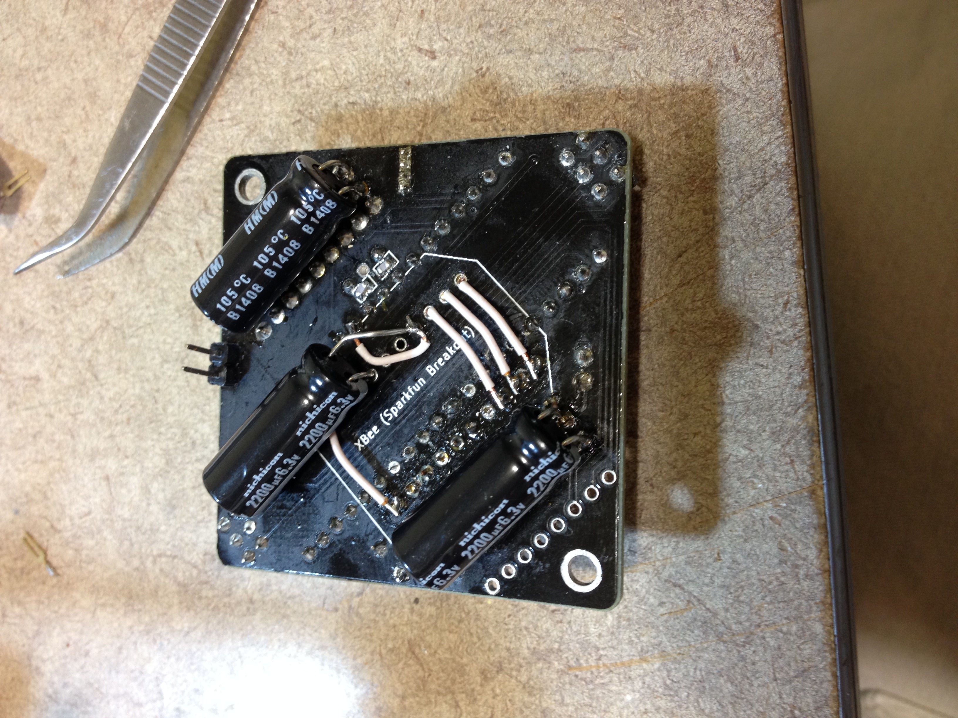
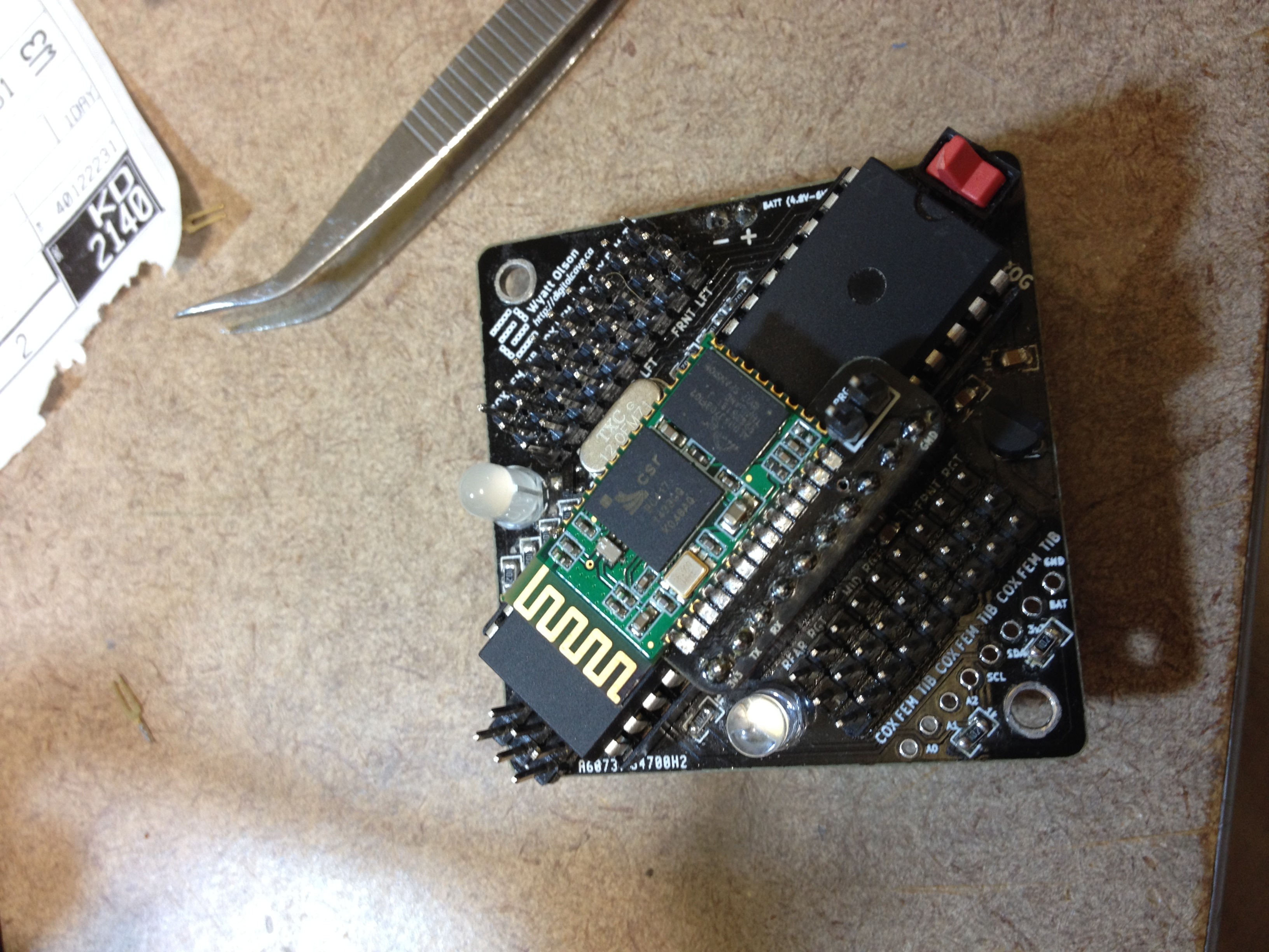
I then proceeded to add the capacitors. I put one 2200uF cap on each side's servo power supply rail, and one on 3.3v:
![]()
(I had already removed the female headers for the radio from the bottom layer)
After I had everything back together again, I re-tested. The results are not perfect, but are much better:
The battery line now does not seem to drop below about 3v, and there is no visible ripple in the 3.3v line. (Eventually I will take a look at things in AC coupled mode with a higher resolution, but for now this is sufficient to show what a very real difference can be made with 3 big capacitors.)
Next, the radio has been moved to the top of the board to allow easy access and swapping. To do this, I desoldered the female headers from the bottom of the board. I then re-soldered one of them on the top (on the row beside the AVR). I soldered some jumper wire between the old and the new headers. The picture of this happens to be the same one as the picture showing off the capacitors, so here it is again (the first three pins are 3.3v, RX, and TX; pin 10 is GND):
![]()
The top side of the board looks a lot cleaner. You can see the headers beside the AVR:
![]()
Finally we have some shots of the control board sporting interchangeable radio modules:
![]()
![]()
Both of these radio modules are attached via custom breakout boards I designed. I am not sure, but I don't think the Sparkfun board would fit here - sorry! :-( I am planning a rev2 board which will have the breakouts included as panelized additions... if I ever finish that, it will be a bit easier to support interchangeable radios.
Finally, the frame needed some work to bring it up to the latest plans. I designed this change a while back, but didn't implement it as it would have entailed taking apart the entire robot, and I wanted to do that along with all other changes (unscrewing lock nuts which have been placed far down a threaded rod takes a long time...)
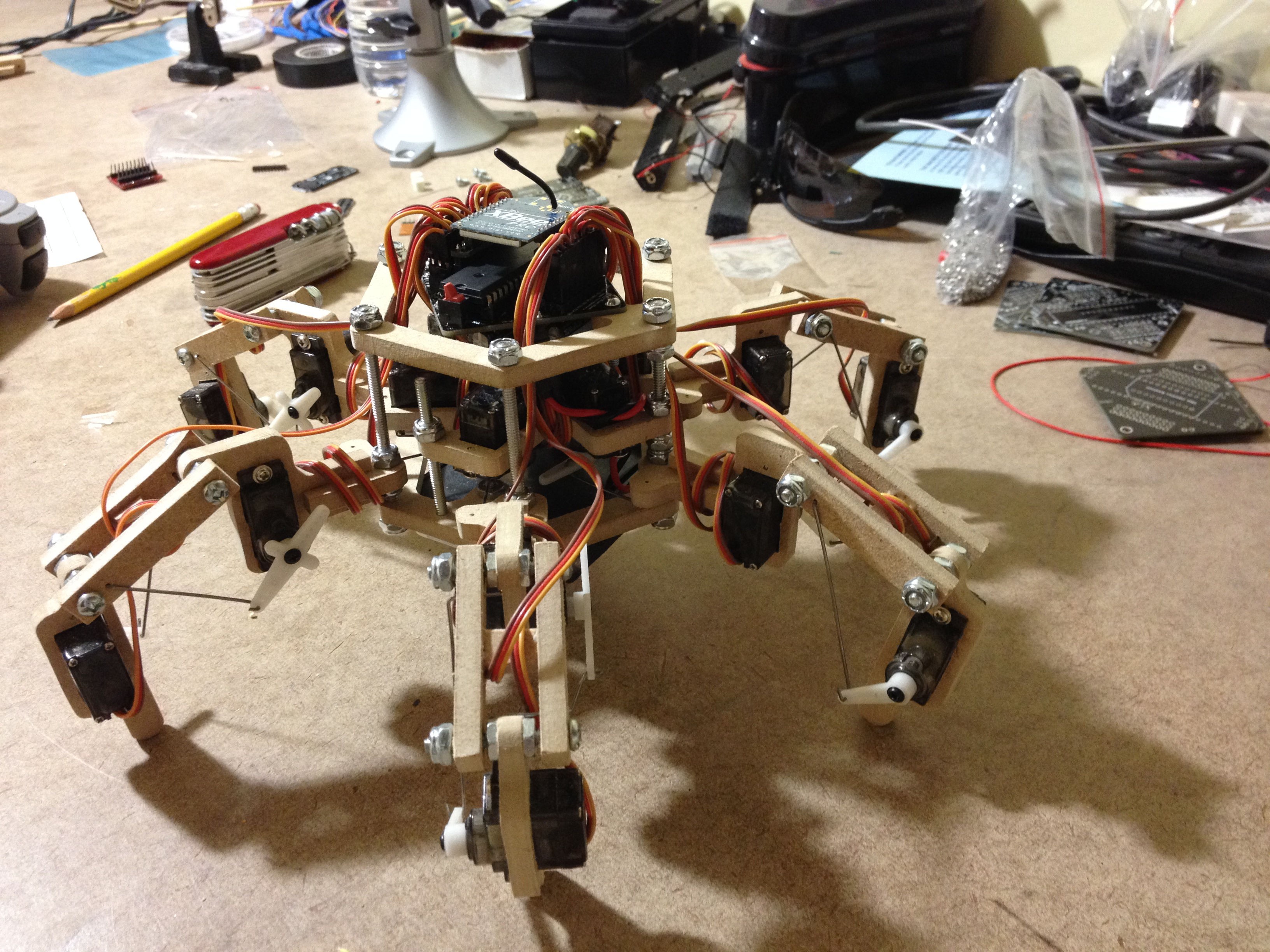
The finished, re-assembled version is here:
![]()
(In particular, node the 2" screws going up from the bottom and through the servo layer. I probably should have used threaded rod and gone through all three layers like I tell other people to do in the plans, but that would have required taking even more stuff apart, and it was getting late already).
Now that I can swap radio modules on the fly, the next step is to verify that the bluetooth module works. I hope to have time for that one tomorrow...
Cheers
-
Reflow Soldering Success
07/13/2014 at 22:35 • 0 commentsToday I successfully completed by first reflow soldering attempt using a heat gun. My first try was with a junk SOIC chip on an extra board I had lying around... it worked perfectly the first time (I ended up with a bit of a solder bridge between two pins, but that easily cleaned up). I cannot test this chip to verify that it works, but I did continuity checks on all the pins and that worked fine:
My second attempt was with a HC-05 (or possibly HC-06... my particular boards have characteristics of both of these boards), trying to solder it to a simple breakout which I designed. This breakout has the same pinout as the Sparkfun XBee breakout, which means that I can use it interchangeably with Stubby to allow it to be controlled by the computer. (This board has quite large pads, and I could have easily soldered it by hand using an iron, but I wanted to practice my reflow technique). This time I was able to actually verify that the circuit worked, by hooking it up to my FTDI cable (via a level adaptor). Sure enough, it works great:
Tomorrow I am expecting to get a bunch of parts from Digikey, which will give me plenty of more practice with reflow soldering, including a nice fine pitched TQFP-32 package.
(This post is not directly related to Stubby, as reflow soldering is not required to build the control board. However, I get to show off my newest skill, and the end result is that I now have a Bluetooth breakout for Stubby, so I figure it qualifies for this project.)
Cheers
-
Ongoing Development Efforts: The Hackaday Prize
07/08/2014 at 20:27 • 0 commentsWhile the main Stubby build is completed, it is far from over as a development and teaching platform. My goal, and the objective of my entry to The Hackaday Prize, is to use Stubby to help teach children basic programming concepts such as calling functions, creating and reading variables, executing control loops, and checking conditional logic. When you are learning to program for the first time, it is much more exciting to see an actual robot bow to your wishes, rather than see 'Hello, World' printing in a text console.
In order to do this, there are a few things which need to be done:
- Replace XBee with a bluetooth module to allow bi-directional communication with a computer
- Connect various sensors (Ultrasonic distance sensor, light sensors, etc)
- Design and implement an API for use with various introductory programming languages (I am thinking things like Python and Wiring at this point) to allow simple interaction with Stubby via a custom program.
Check back often, or follow this project for updates!
-
Updates to the Component list + Assembly Instructions
07/04/2014 at 01:29 • 0 commentsCheck out http://stubby.digitalcave.ca for an updated component list (including Digikey part numbers), assembly instructions with pictures, calibration directions, and inverse kinematics theory.
You can also browse the git repos from a web browser now, no need to clone the entire repository.
-
Project Completed
06/30/2014 at 01:13 • 0 commentsAfter a couple days of marathon coding, Stubby v3 is now pretty much complete. You can move in any direction on the XY axis, translate the body on the XYZ axis, and roll the body on the XYZ axis. See all this and more in the demo video:
Check out the website at http://stubby.digitalcave.ca for detailed component list, build instructions, schematics, etc.
If you have any questions / comments please let me know in the comments, and I will be happy to respond.
-
Tripod Gait Working
06/26/2014 at 18:02 • 0 commentsStubby v3 will be controlled similar to a video game: use the left stick for forward / backward / strafe right + left, and use the right stick to turn. So far, I have the left stick working properly, using a straight tripod gait.
From an implementation POV, each leg knows its "neutral position", i.e. the point which it should be at when at rest. I then have a lookup table of offsets, which are to be applied to the neutral position for each leg, which moves the leg in a roughly circular motion (with the bottom of the shape being flat, of course).
The main loop keeps track of the step index, which is used to index into the lookup table. Velocity information is scaled in at this time, and the offset point is returned.
The resulting point is then rotated on the X,Y axis to allow for walking in any direction.
The next major step is to create a similar lookup table for rotation, using the right stick, and then to factor the two points together so that you can rotate and walk at the same time. I think that doing another offset should be sufficient, although further testing will definitely be needed here.
(And on another note, it appears that I have plenty of CPU cycles left over, even after driving the PWM, doing IK calculations, and gait generation; in fact, I need to include a delay in the gait loop or else the main loop runs too fast for the servos to keep up! It is amazing what you can squeeze out of a 12MHz AVR! Of course, the recent changes to the PWM library which reduced the time needed in the most frequently fired ISR by about half didn't hurt either...)
More videos to come when I get a bit more stuff working.
-
Y Axis Translation demo
06/20/2014 at 21:40 • 0 commentsToday I finally worked out all the bugs in the IK and servo driver software. This now allows me to set any leg at an absolute x,y,z co-ordinate (within reason, of course... there are physical limits to how far each leg can move). To demonstrate this, I have a video of Stubby's body moving along the Y axis without the feet moving (or more accurately, all of the feet are moving along the same axis at the same rate, essentially moving the body).
I think the next step (no pun intended) will be to create another abstraction which will convert body commands (move forward, turn, translate body on X axis, etc) into a series of leg commands. This may end up being another IK-style library, or it may be something like an animation (just a series of steps)... I am not really sure of the best way to go about doing this. If anyone has a recommendation, please let me know in the comments!
Stubby the (Teaching) Hexapod
100% open source robot platform with accessability and affordability in mind: teaching children of all ages about robots & programming