 DeepSOIC
This project is a theory part of #Ion wind loudspeaker experiments project.
Before you start reading this BS, take a look at some conclusions.
Conclusion 1. Pressure (thrust), length, and current are directly related:
where M is the mobility of ions in air (a constant).
Conclusion 2. To support a certain current through the drift zone, a minimum voltage to overcome space charge is required, given by:
Conclusion 3. Because of the limit on E-field that the air can withstand (breakdown), the maximum pressure that can be achieved is about 40 Pa. This limit does not depend on the length of the drift zone, so the zone can be squeezed. That also lowers operating voltage, but requires increasing current.
Read on if you are interested how did I get these conclusions.
Assumptions
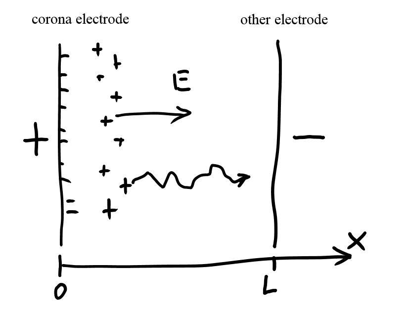
1. Geometry of flat capacitor. Plates are large compared to the distance between them.
This is certainly false, because of the way corona electrode is made, but I’m really simplifying things to draw simple estimates.
2. Charge density is even across the surfaces of the plates, current flow is even. So, charge density is a function of x: ρ(x)
3. Ignoring airflow speed.
justification:
mobility of ions in air is 1.95E-4 m2/V∙s
I am dealing with electric fields of about 5kV/cm, that is 5E5 V/m
So, ions fly at speeds of about 100 m/s. Airflow speeds in the drift zone are unknown, but probably not much higher than a few cm behind the blower. These are less than 10 m/s. And, introducing airflow speed makes diff. equations not solvable on paper.
4. I am ignoring corona region, and I am just assuming corona electrode is a flat plate that emits positive ions with a fixed current of I (per square meter of surface). I am also assuming there is no voltage drop in the corona.
These assumptions are certainly false, but I want to obtain approximate figures.
Time to write some equations.
Symbols:
L = distance between plates
x = coordinate. corona electrode is at x=0, other electrode is at x=L
ρ (x) = charge density distribution (concentration of ions in air, expressed as coulombs/cubic meter)
E (x) = electric field distribution (E vector is always along x, thanks to assumption 2)
v(x) = Drift speed. That is, average speed of ions in meters per second due to electric field.
M = mobility of ions in air (that is, the speed the ions penetrate the air in unit electric field)
Basic equations of processes
Equation 1. Continuity equation: current is equal through any vertical section:
𝐼=𝑣(𝑥)⋅𝜌(𝑥)=𝑐𝑜𝑛𝑠𝑡
This equation represents a requirement of steady-state condition: no charge can continuously accumulate in the air, or be drawn from it.
Equation 2. Charge density and electric filed are related:
Equation 3. Drift speed and electric field relationship.
Equation 4. Boundary conditions: a voltage U is forced between the plates
Solution
Solving the volume (ignoring boundary conditions)
substituting eq.3 into eq.1, we get:
substituting eq.2 (solved for ρ) into the previous, we get:
Now we have a differential equation for electric field vs x, that can be solved. The solution is:
here, x0 is an arbitrary constant of a dimension of length, a degree of freedom of solution. For our geometry, x0 is non-positive, for the solution to be real-valued everywhere.
Now, let’s apply the boundary condition to get rid of this degree of freedom.
Solving boundary condition (fail!)
Substituting the above solution into boundary condition, we get an equation:
We are to solve it for x0.
Taking the integral:
expanding the substitution:
This doesn’t look solvable. So what we can do is to express key values as a function of x0, using it as parameter for plotting later.
Key values as function of degree of freedom x0
Current:
charge density:
Total charge of flowing ions:
Pressure
Now, let’s calculate the pressure. Here, we make an important assumption, that the momentum of ions hitting the other electrode can be ignored. This is because mean free path of molecules (and ions, too) is very small. So the ion will have crazy number of collisions with air, before it reaches the other electrode. So, we can conclude, that the pressure exerted to the air is equal to total force of the field dragging the ions. So,
Remember that equation that we had long ago?:
The quantity we are integrating is constant, the integral is trivial! So we have a very simple, yet interesting result:
So, the pressure is basically a product of length of the drift region, and the amount of current we managed to push through it. Surprisingly, there is no direct dependence on voltage. However, as we are about to find out, to push some current, we need some minimum amount of voltage. Let's calculate it!
Limit: I-V curve of drift region
Looking up the solution for E, that condition corresponds to our degree-of-freedom parameter x0 = 0. And the solution for E is:
This is our I-V curve of space-charge-limited drift zone:
Key values when current is limited by space charge screening
E-field distribution:
Total charge in the air:
Pressure (thrust):
Note that the max pressure depends on a ratio U/L, which is directly related with maximum electric field in the drift zone. Since we can’t have arbitrarily high electric fields in air – the air has a breakdown threshold of about 3E6 V/m. The air with ions probably has a bit less, but I’m not sure. This maximum electric field corresponds to a pressure of 40 Pa. That’s quite a lot, actually!
Another conclusion from this relation is that we can decrease both length and voltage of the drift region, without affecting maximum pressure. That is, we can build as thin a system as we want, until we hit the mean free path, without losing maximum performance. And we’ll have an extra benefit of decreased voltages, at the expense of more current. Cool!