 David Scholten
Finally, after weeks of umming and arrring, the schematic is done!
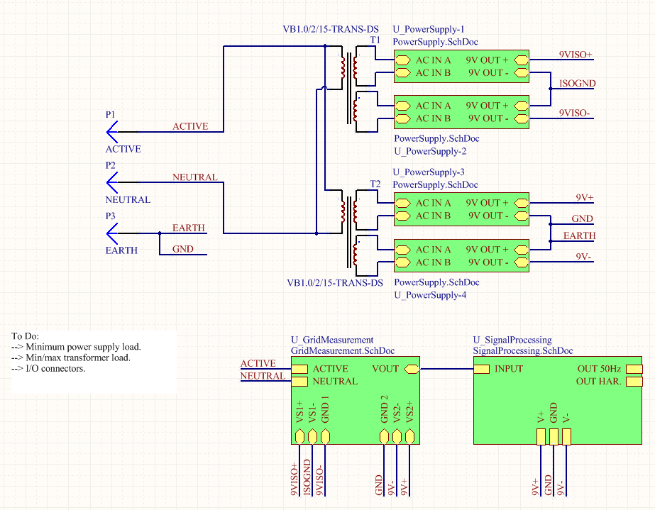
The overall design of the system has remained unchanged with the exception of the input filter. Originally, there were plans for an input LC low pass filter to reduce the harmonics and fluctuations in the mains supply current, which would result in measured voltage harmonics in the system. This is due to the resistance of the input IEC cable. Here is the final system hierarchy with the LC filter removed:
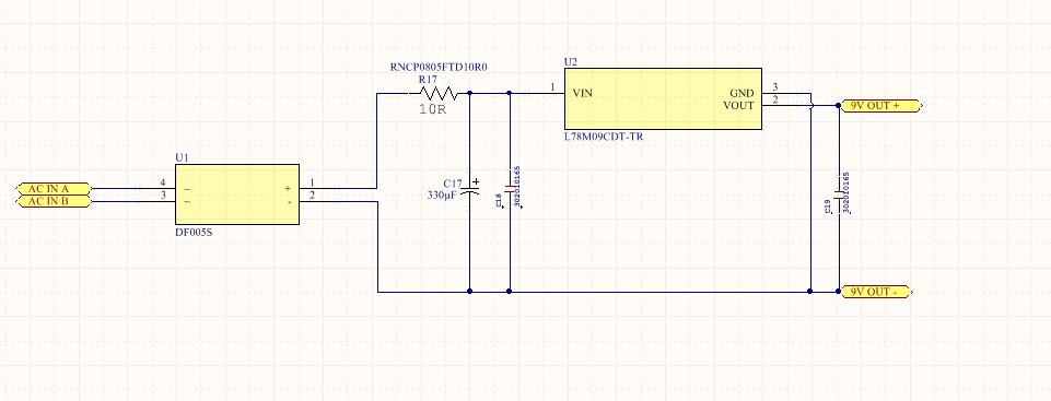
To compensate for the lack of input filtering, the power supplies have been modified to include a series resistor to limit the 100Hz “inrush” current to the electrolytic capacitor. Each half cycle there is a rush to “refill” the capacitor, which results in a sudden impulse of current. The series resistor limits this current and dramatically increases the charge time of the capacitor. This thereby reduces the peak current and the voltage harmonics due to the IEC cabling resistance. However, this does reduce the minimum capacitor voltage and the transformer turns ratio has been adjusted to compensate.
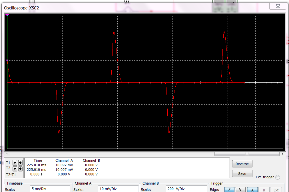
The mains current before the series resistor is added:
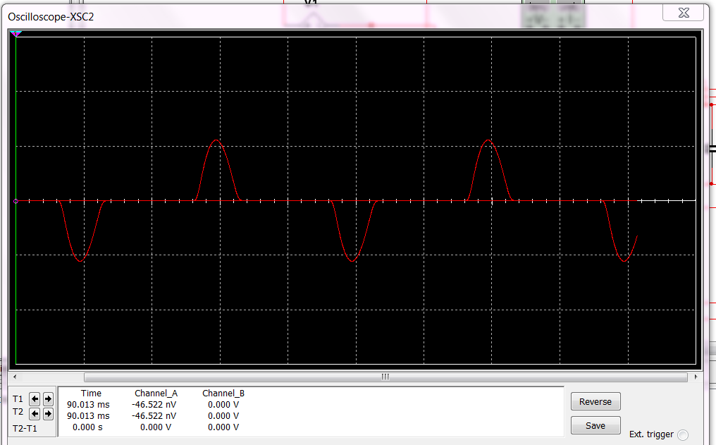
After the resistor is added:
Other than this factor, the power supplies (+/-9V x2) are quite basic and remain mostly unchanged:
The signal acquisition block of the hierarchy takes the grid voltage and produces a safe, isolated, 4V copy to send on to the signal processing block:
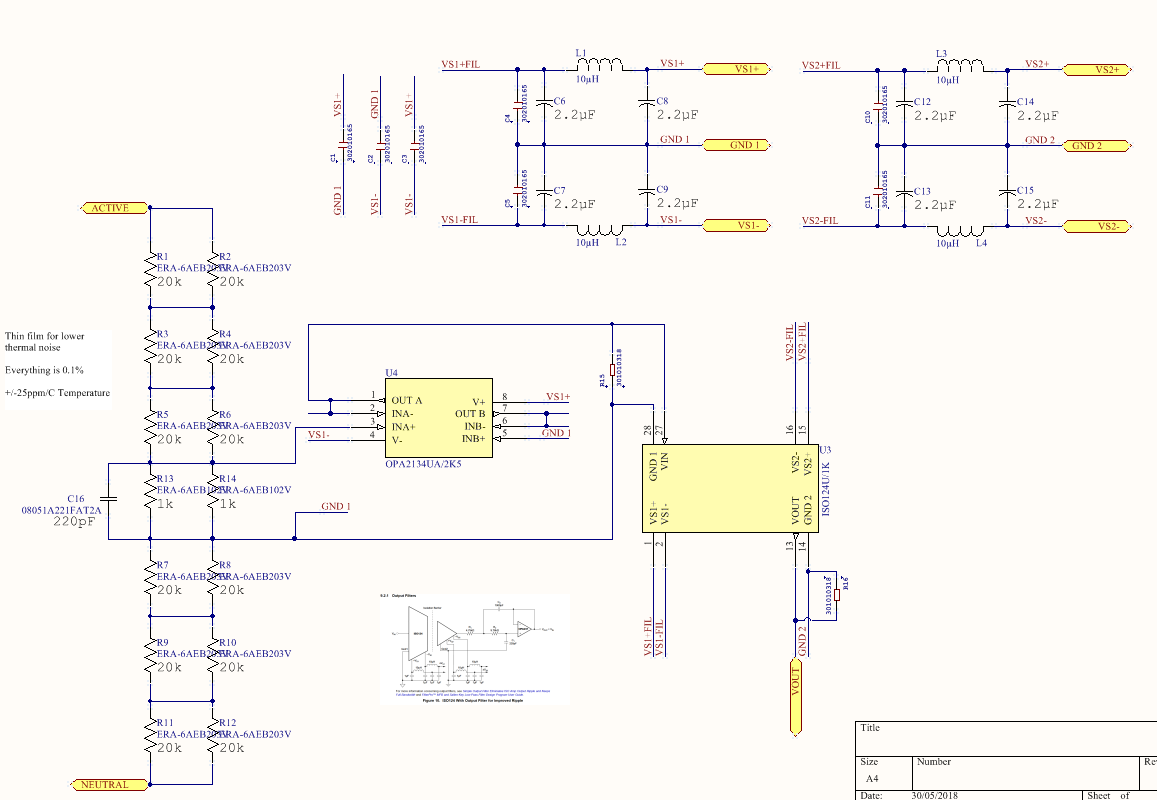
First, the voltage dividers reduce the mains level down to the 4V level. Using such large value resistors (power dissipation limits) has the potential to introduce thermal noise at this point, so the thick film type resistors were used to alleviate the issue. The 4V signal is then buffered by an OPA2134 op-amp and fed to the ISO124 isolation amplifier (lower input impedance), which provides near-galvanic levels of isolation. One of the many drawbacks to the ISO124 is the practical requirement for 4 separate power supplies (two of which are isolated from the other two) to drive it. Additionally, the ISO124 leaves the signal with a 20mV (0.5%) DC offset, a very low current driving capability (<10mA) and a 10mV (0.25%) 50kHz ripple.
Signal processing time (some resistors and caps have not been selected):
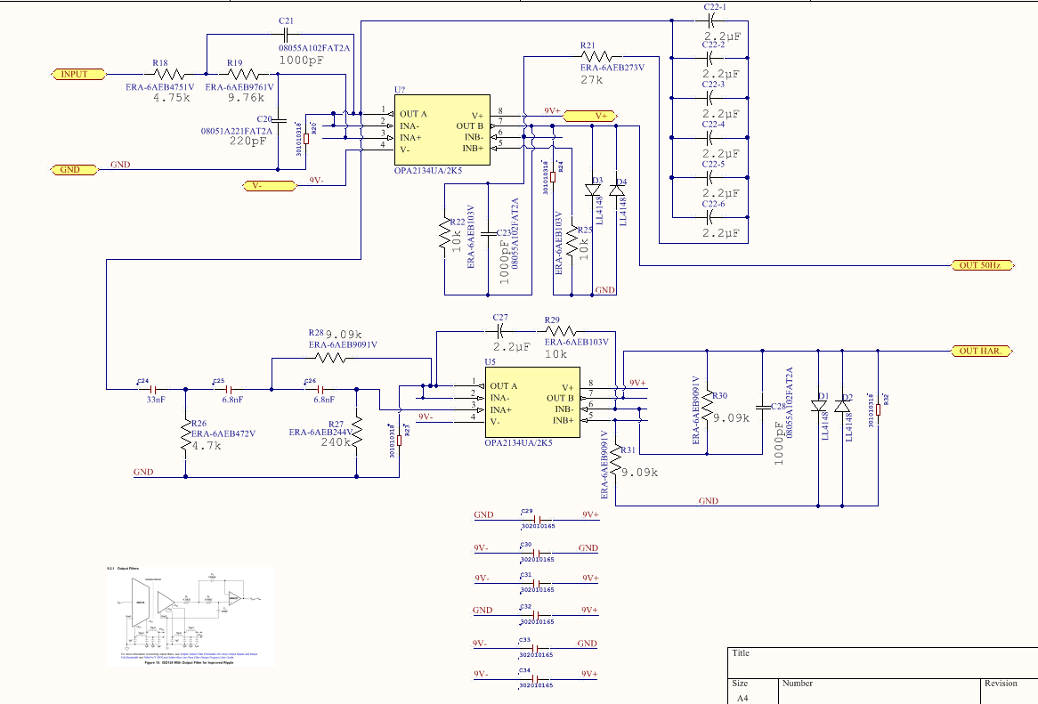
The signal processing hierarchical block takes the 4V signal and applies a 2nd order low pass filter that works in conjunction with the internals of the ISO124 to produce a 3rd low pass filter to remove the 50khz ripple. This signal is then sent to an inverting amplifier to reduce the signal magnitude to about 450mV peak and provide increased current drive capability. In addition, this op amp also removes the DC offsets that have accumulated and removes any RF interference/noise (1.5MHz 3dB point).
The 4V signal is also sent to a 3rd order high pass filter for a harmonics only output (500Hz+). After this the harmonics-only output is sent to another op amp to increase the signal magnitude to a matching 450mV peak output (along with DC offset removal and RF reduction).
The final outputs are/will be scaled (approximately) such that:
Main output: 0-450mVp is 0-423Vp (50Hz to 20kHz)
Harmonics output: 0-450mVp is 0-20Vp (500Hz to 20kHz)
The frequency range does expand up to 50kHz (-3db), but it only remains flat until about 30kHz. As sounds cards (mostly) cap before 20kHz, I only concerned myself with the bandwidth under 20kHz during the design process.
Sorry for the incoherence throughout the post - It was written quickly in many chunks ;)
Discussions
Become a Hackaday.io Member
Create an account to leave a comment. Already have an account? Log In.