 jaromir.sukuba
I set a few basic goals for this progmeter:
1, PCB has to be under 25,4x25,4mm in size to fit the rules of #The Square Inch Project
2, To be able to measure at least basic ranges of voltages and current. Say 20V and 10Ohm to 1Mohm with reasonable accuracy, say 1%. Some amount of foolproofness is required.
3, Completely battery powered
4, At least rudimentary math operations above the measured results.
Now, let's analyze it: The first point is nothing special in this phase of planning, just set PCB outline to 25x25mm. Third point is somehow complicating the first task, as the battery or charging circuit has to be placed on PCB. Last point precedes using of MCU, display and few buttons as user IO (opposed to using "dumb" ADC driving display). In fact MCU simplifies some hardware aspects of progmeter, as will be seen later.
Second point is where the fun begins.
Analog part
Measurement of voltage is fairly simple, just take an ADC. Internal ADC of most of MCU's would be sufficient, to some degree. If I'd use 10-bit ADC, for 20V range I'd get around 20mV resolution (20V/1024 levels) which is not bad, but not that great on voltages below 2V. Usage of external ADC allows better results. 12-bit ADC is marginally good, but higher resolution ADC's are not that expensive those days. MCP3421 costs 2EUR in single quantity locally and is switchable from 18-bits to 12-bits, allowing compromise between speed and resolution. So, we have ADC and voltage divider - in fact, voltmeter.
Resistance measurement is a little bit trickier. The most obvious method requires precise current source with known value and voltmeter to measure voltage drop on that resistor. Note that resistor instead of current source will not work, as current flowing through unknown resistor will vary with the DUT resistance. If I could measure the voltage drop on that known resistor, I can calculate current flowing through it and subsequently unknown resistance.
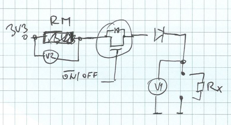
When MOSFET is on (its gate is grounded), current flows from 3V3 source through Rm, diode and Rx to ground. Voltage drop U1 on Rx is measured by voltmeter V1, Rm is known and voltage drop U2 on it is measured by V2. The resulting resistance is
where so that
Diode serves as simple overvoltage protection and is not needed by principle of operation. Resistance range from 10Ohm to 1MOhm spans through five decades and single resistance range will not cut it, obviously. Adding another resistance range makes it simpler, requiring two and half decade per range and this is bearable for low-spec device. The resulting schematics for resistance measurement will look like this
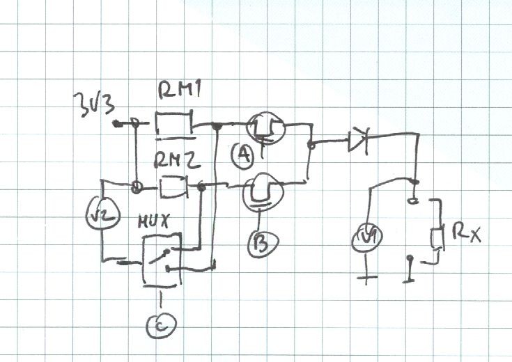
Now let's put it together:
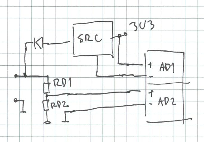
Now I have completely analog-to-digital frontend. ADC communicates via I2C bus and MUX / MOSFET control lines are simple 3,3V digital lines.
Digital part and board space
I opted to use some low-end 8-bit PIC MCU for this task. In fact,I could use anything with a few IO lines, but this is the simplest way to make it working what is fine when making time constrained contest entry.
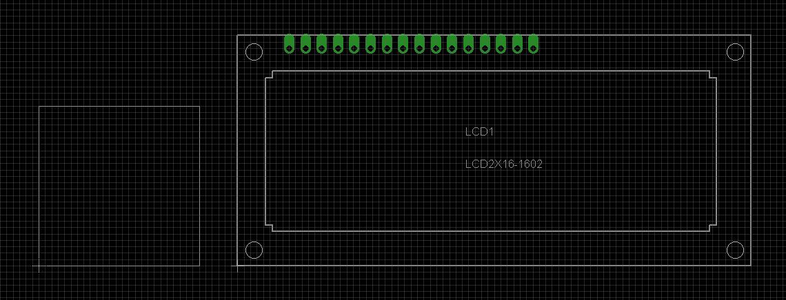
For user IO there is not much of choices, given the fact I have to cram it into 25x25mm area. This is now classical 16x2 LCD looks next to 25x25mm square.
Meh. I have to find something smaller.
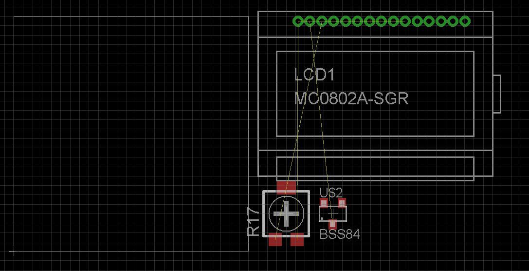
This is how the MC0802-SGR display - I used it in #Mini Altimeter - looks, with trimer and switching MOSFET.
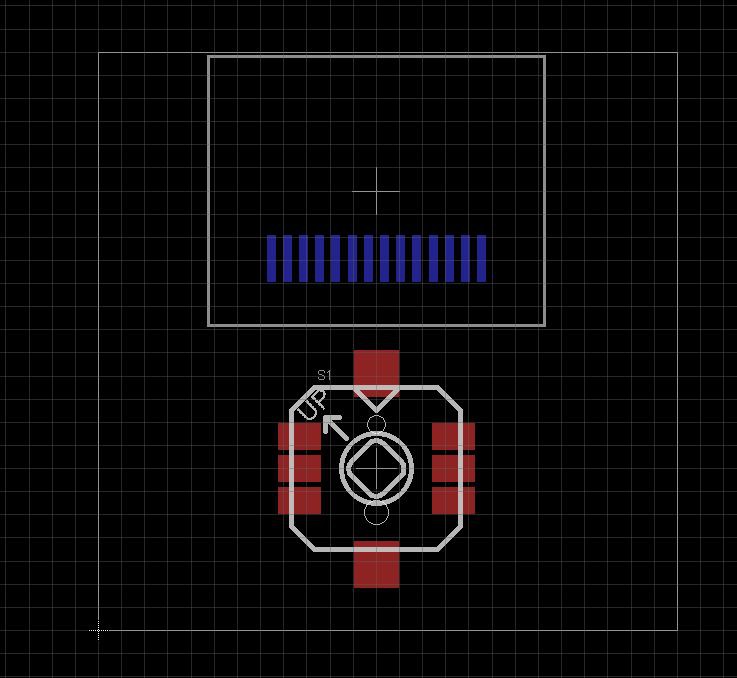
Better, but still way too big. Then I remembered I found 0,49" inch OLED on aliexpress and bought it, thanks to my slight compulsive hoarding disorder. Coupled with micro joystick it looks like a nice couple
 Let's add some MCP73831 for Li-Ion charging and micro USB connector and we have it!
Discussions
Become a Hackaday.io Member
Create an account to leave a comment. Already have an account? Log In.