-
Math (Part 4). Or how I stopped worrying and learned to love Stuxnet
10/27/2015 at 02:28 • 3 commentsSo last time I learned that a single stage centrifugal disc pump with edge speed of 2000 m/s could achieve all of my lofty goals. Turns out this is actually really hard to do in real life.
A few years back most of you will remember the Stuxnet virus that hit Iran. It targeted their aluminum centrifuges being used for isotope separation, and caused them to overspeed. When a spinning cylinder (or disc) is spun, the centrifugal force on the material itself causes "hoop stresses" to be set up along the circumference. When this hoop stress exceeds the tensile strength of the material, it separates into several constituent components which travel in a straight line because Newton. They explode.
The math that describes this is actually surprisingly simple (when you let other people do the derivation for you!):
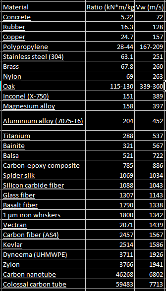
Where Vw is the tangential velocity of the walls (same as the last post), sigma = tensile strength of the material, and rho is the density of the material. Sigma/Rho is also known as specific strength of "strength to weight ratio". Throwing in some numbers I got from Wikipedia, here's a brief list of edge velocities for various materials:
![]()
So, it looks like no known material (that can be made into a large disc) can stand up to 2000 m/s rotation. Hence the need to look at multiple stages for this design.
What's neat about this relation is I can simply look at what materials are readily available to me, and design the rest of the pump parameters around that. Vw max directly correlates to the number of pump stages you will need to reach goal total compression ratio (see the last post). Initially, carbon fiber composite looks like it's going to be the best option, I wonder if you can laser cut that? Balsa doesn't look too bad either, but it's strength is probably highly directional with the wood grain, so may not hold up as well in practice. Plus wood does pretty bad in high vacuum (lots of off-gassing). Aluminum is not nearly as good as I thought it would be, but would be easy to machine if someone had a CNC.
By far the best would be individually wrapped carbon fiber strands, with no (or very very little epoxy). That's how lightweight flywheels are made for hybrid cars, with the fibers wrapped circumferentially.
-
The Theory, and some Maths (Part 3)
10/26/2015 at 18:08 • 0 commentsLast time I offered this equation as a rough description of the pressure gradient inside a disc pump:
Now I'd like to do a study in compression ratios with some real numbers, to get an idea of how this math will drive the design. To start, we'll do some algebra to make this spit out the compression ratio:
Interestingly, the compression ratio achieved from one pair of discs (this will be one "stage" in our pump) primarily depends on Vw, the tangential velocity of the outside edge of the discs. So, large discs spinning kinda sorta fast could have the same compression ratio as small discs spinning super fast. For my goals, I need a total compression ratio of 7.6x10^9, to go from a vacuum of 1.33x10⁻⁵ Pa to atmospheric pressure of 1.01x10^5 Pa. So, given a specific edge velocity Vw, I can figure out how many stages I need to reach my goal with this:
I made that one up, I think it's right, but not completely sure. I lost the scrap of paper I derived it on, haha. Documenting is so much work! Here's a table I made of what this looks like for various Vw's:
![]()
As you can see, faster Vw is exponentially more better. So why don't we just spin one disc at 2000 m/s for a single stage pump and call it a day? Tune in next time...
-
The Theory, and some Maths (Part 2)
10/26/2015 at 17:23 • 0 commentsWe left off with some useless equations for incompressible flow. Well, I guess they'd be useful if anyone wants to build a water pump out of a Tesla turbine. The author also provided an equation for compressible flow:
Where K= ratio of specific heats, which is 1.4 for air. M is the mach number, but it is unclear to me how to estimate the Mach number. Mach is the ratio of flow velocity to the speed of sound, however In one part of the paper he uses the flow velocity at the inside radius (radius of the intake hole), in another part he uses the outside radius (MUCH higher Mach speed). Also, I have no idea what Pr is. Presumably it is the static pressure, but at what point? (intake or exhaust?) He doesn't actually use compressible flow for his application in the paper, so without an example to follow I don't know enough about fluid dynamics to figure it out. If there are any aerodynamics gurus reading this that can shed some light for me that'd be awesome!
In the meantime, I'm going to take a different route. Ideally, the air isn't really flowing past the discs much at all, but is stuck to them and slowly migrates out radially as it picks up speed. If we assume this "no slip" ideal case, and take our reference frame to be the discs themselves, then we essentially have an acceleration gradient. Gases subjected to high speed rotation show up in another application, gas centrifuges for isotope separation. Turns out this is a fairly well studied/understood topic, and I found a paper with just the equation I need. I'll skip the derivation here, look to the paper if you are interested. This is the simplest set of assumptions, what the paper calls "Iso-thermal rigid body rotation":
Ps(r) is the static pressure at radius "r", Pw is the pressure at the wall of the cylinder, M is the molar mass of the gas (.028964 kg/mol for air), Vw is the wall velocity (Vw=omega * radius of the cylinder), R0 is the general gas constant (8.31447 J/mol), and T0 is the average gas temperature. In a centrifuge, this initial equation must be modified to account for the length of the cylinder, as the effect of drag from the end caps diminishes towards the middle. In our case however, our two "end caps" are actually the discs, which will be VERY closely spaced, so the rigid body rotation assumption should actually be a fairly good approximation. I hope.
The paper from which this equation came notes that this only holds true down to the Knudsen flow range, where molecules stop interacting and pushing on each other. Normal flows due to pressure gradients don't really work the same here. I have been unable to find anything in the literature describing Knudsen or molecular flow in a Tesla disc turbine, so I don't really know if this will continue to describe my pump's operation below this range. However, molecular drag vacuum pumps are similar in construction to Tesla pumps, and are specifically designed with very small channel dimensions, so that the flow remains molecular into relatively high pressure ranges. This indicates that the function of the pump may actually improve at very low densities.
Next I'll plug in some real numbers and get an idea of what size to shoot for in the prototype.
-
The Theory, and some Maths (Part 1)
10/24/2015 at 14:12 • 0 commentsI don't actually know much about fluid dynamics, and could not hope to do an accurate CFD simulation of this myself. Luckily, in 2008 [Peter Harwood] wrote a very nice paper accomplishing this for bladeless turbines operating as air compressors or blowers, however the applicability of his equations to the molecular flow regime seems to be completely unexplored in the literature. The main equation I got from him is the math governing Pmax, or maximum back pressure. This is in theory the maximum pressure differential that the pump can sustain before flow starts reversing.
With rho = Density of air (1.225 kg/m^3 at atmospheric pressure), omega = angular velocity (in radians/second), and r_o and r_i are the outer and inner radii of the discs respectively.
While this was a good start for me, there seem to be some conceptual issues with applying this equation to vacuum pumps. The first problem is that this yields only a pressure differential, without taking into consideration the intake pressure. Mathematically, we could surmise that:
This is obvious, and was experimentally verified by [Harwood] for his application, with 1x10^5 Pa (Pmax) = 2x10^5 Pa (Exhaust) - 1x10^5 Pa (Intake, atmospheric pressure). For vacuum however, we could arbitrarily set:
Even more dubious, the resultant compression ratio looks like this:
With some numbers plugged in, just to get an idea of realism, this implies that a 22cm diameter disc at 35000 RPM could reach an arbitrarily low vacuum (10^-a billion Torr?) in a single stage. The reason this sounds unrealistic is that the math is wrong. We have not accounted for the variable density of air from intake to exhaust. The previous equation assumed incompressible flow, and for this application we are very much interested in compressible flow, for obvious reasons. More on that in Part 2.
Everyman's turbomolecular pump
(Maybe) access to the high vacuum environment for the rest of us