 Alex
AlexAs written previously on this page. I did some PCB layouting on this project. First more to test whether it is possible to make an drop in replacement out of a tiny PCB with the same size as the original TIL311. But think I did now have a first version ready. I did first started with tiny 0201 LEDs but I think they are very difficult to solder. So I moved over to 0402 LEDs. This also brings you bigger numbers with less LEDs. Here some renderings (created with eagleUP and sketchup) of the PCB:
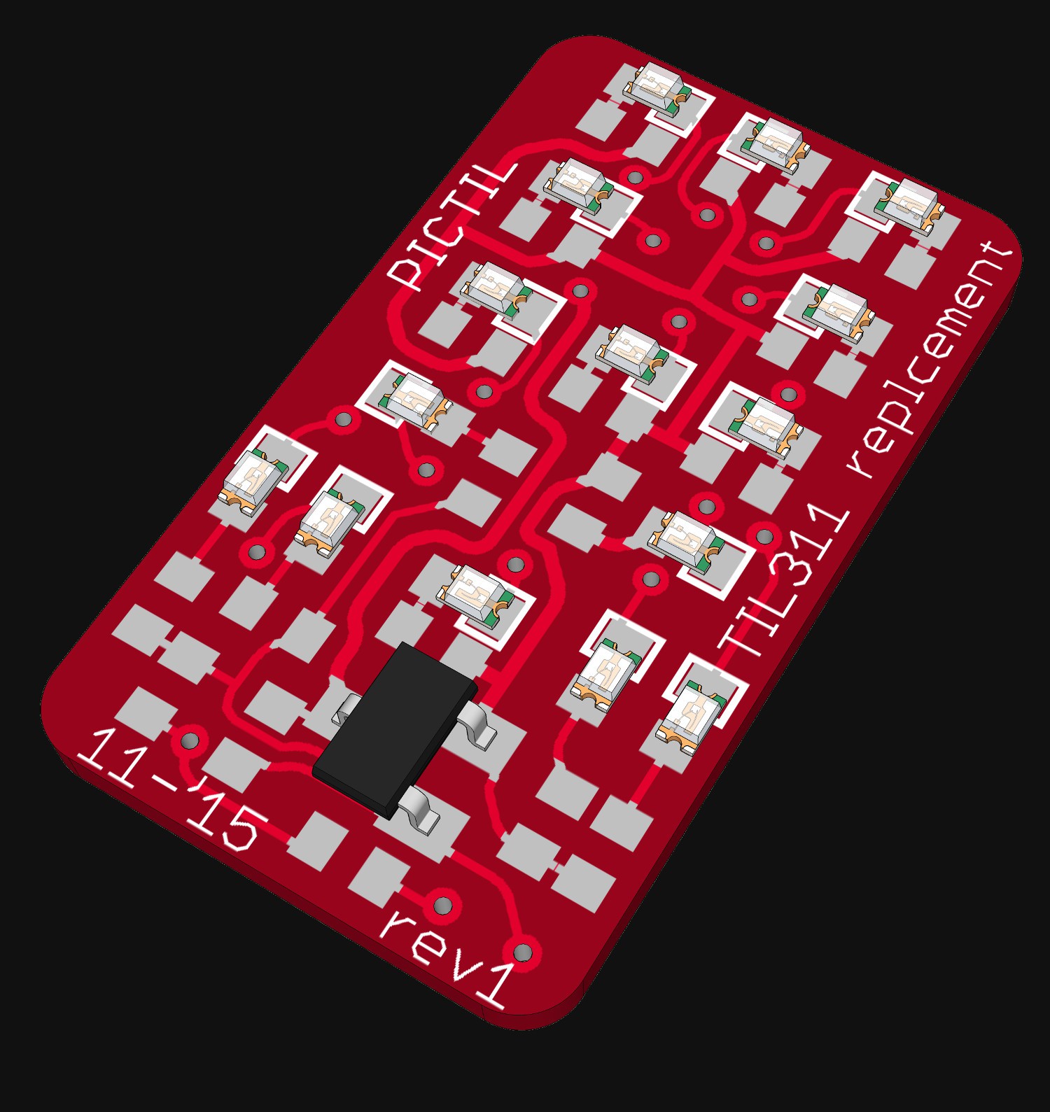
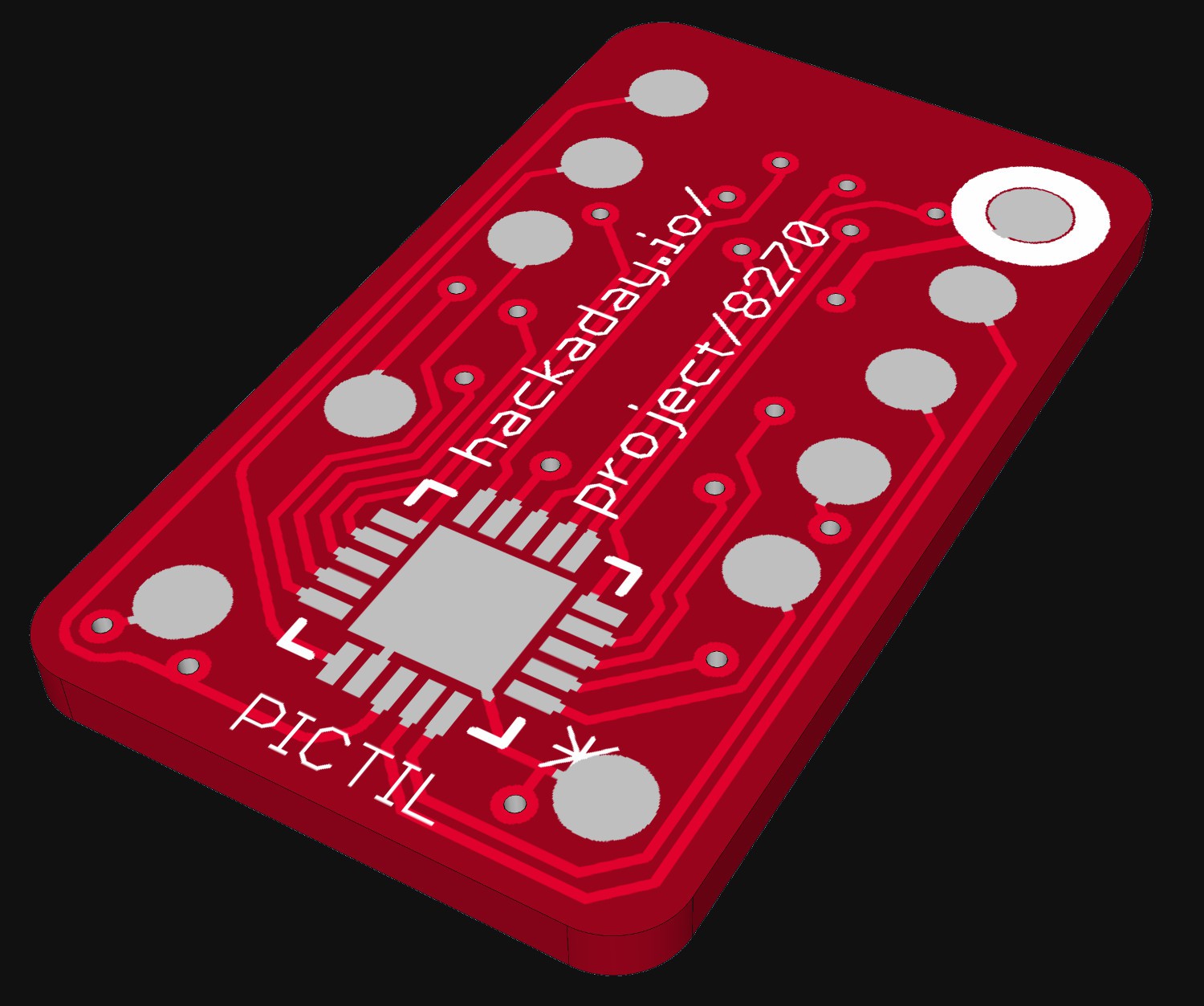
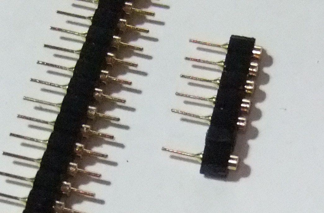
In my design I used the PIC suggested by @Yann Guidon / YGDES. And a p-channel mosfet to get the blanking function. The mosfets and the LEDs are on the top side and the microcontroller on the bottom side. As you can see on the picture pin headers must be SMD. There was no place left over for THT pin headers. Sadly pin headers like these does not exists (correct me please if I am wrong). But you can make them yourself out of more normal THT ones. Here a picture of a test (on the left the original and right the modified for SMD mounting):
So that was all for today. If you have any suggestions, ideas or found mistakes please let me know.
Discussions
Become a Hackaday.io Member
Create an account to leave a comment. Already have an account? Log In.
Looking further, I see you use the P-FET instead for blank. I advise to add a diode on the base so you don't force the driving circuit to be "open collector" only.
The Latch pin can work but not at the speed advertised by the datasheet. This is why I didn't include lathing as a requirement when looking for a PIC. A FPGA would work but is an ICe40 (like in the #DIPSY ) overkill ?
For the pin : clever idea. We might find something suitable. I've got golden pins on eBay, they still require a tiny hole, maybe there are other shapes for surface mount. There is the risk however that the surface mount pins get unsoldered during mounting on another board... Higher temperature solder would be required, maybe.
You have assigned ICSPDAT and ICSPCLK to user-facing pins so no special adapter (pogo pin?) is required for programming, that's another smart move (I imagined allocating them to LEDs and using pogo pins but that was dumb).
Can you put some resistors on the IC side too ?
Are you sure? yes | no
Do you mean an diode between the gate and GND or where? Or between the base and the PIC?
Yes the speed of the latch pin should be not fast. So itsm ore an extra for low speed circuits. The latch pin is connected to the reset pin of the PIC so it can be also used as reset (if this pin is programmed as reset this is a blanking alternative). - I did also thought about fpgas. They would fit great, but: Most of them do not have 13 IOs wich can source an LED. but I do not have an good market overview on fpgas. And I do have less experience with them.
Drilling an hole would cost space. And so far my goal is to use the same size for the PCB as the original TIL311. To avoid the unsoldring I was thinking of glue, but this glue should resits high temperature. The idea with other solder is also good.
I need the backside mostly for the pins and the PIC. I do not think that it is possible to put many of them on the back, but some could fit.
Are you sure? yes | no
I mean a diode between the pulled-up gate and the external pin.
If Vled is not powered, then a high level will inject some (tiny) current through the pull-up, which might eventually display ghost light. It might also polarize the P-FET that could become conducting.
Concerning FPGAs, the ICe40 family has really tiny chips, the smallest has only 16 pins in incredibly fine BGA. PIC are more popular though. Some pins can source some current but our modern LEDs don't need crazy current. We're not doing "lighting" so 1mA is often enough and Vled can control that.
Silicon and epoxy polymers can resist high temperatures (that's what FR4 is made of, BTW). It might be a good solution but I don't know which product is best suited for this exact case.
Are you sure? yes | no
That is simply amazing. How does it look with 0603 ?
For the programming : the Vpp is generated by the programming device. In my idea, the PIC is "controlled" by the /reset (/MCLR) pin to force blank (indirectly) [I haven't checked the datasheet whether it also clears the I/Os or simply restarts to address 0]. This external pin is also used for feeding Vpp to the chip so there should be no difficulty or interference. I think a pull-up on /MCLR is required, maybe there is an internal pull-up.
Are you sure? yes | no
Mh.. I did not try 0604 yet. But 0603 for LEDs and resistors would not fit, as far the PCB'S dimensions are the same.
Are you sure? yes | no
I'm not sure I can solder 0402...
Are you sure? yes | no
0402 aren't that bad for reflow. You can save a bit of space by using resistor network.
Are you sure? yes | no
isn't a pic programmed with 12V? did that complicate things?
Are you sure? yes | no
as far as I understand them, you just have to use the right programmer
like the PICKIT2. I think the 12V are generated by the programmer. But I
do not have any experience with PICs yet. But I will order some PICs
soon, then I will know.
Are you sure? yes | no
If you are unsure, you can always refer to documentation ;-)
http://ww1.microchip.com/downloads/en/DeviceDoc/41640A.pdf on page 4, fig 3-1 MCLR has to be pulled to Vihh level to enter programming mode, on page 21 there is Vihh as Vdd+3,5-13,5V, so PicKit2 has to apply something around 12V on MCLR in order to program it. Because MCLR/RA3 is used as input and nothing else it should be accessible with no problems once the PICTIL is out of circuit.
Are you sure? yes | no
thanks!
Are you sure? yes | no
Once we have decided which chip to use, I'll have to check the compatibility with my own old tools. I should have no particular problem, I sometimes fake a part by using another file header, for example. Since we won't use too many chip-specific features, it will be easy to port to other chips.
Are you sure? yes | no