 Tim Wilkinson
The robot arm consists of a bunch of aluminum brackets, bolts, and 6 servos. As with all servos, these are managed using a pulse-width control scheme (PWM). Because the arm is consider a payload for the ROV, it should operate using the payload bus connector (see a previous post about the "bus"). To make this happen, a little electronics is necessary to convert the I2C payload bus to a set of PWM signals, and also convert the 12V bus "mains" to the 7.4V needed by the servos.
Rather than build a custom board for this, I used two boards I had around the workshop. The first is a I2C PWM board from Adafruit. This allows me to control the servos using I2C. The second is a buck converter from eBay which converts the 12V down to 7.4V. To keep the mounting tidy, I used my PCB router to make a simple inter-connect board, and then mounted the two main boards to that.
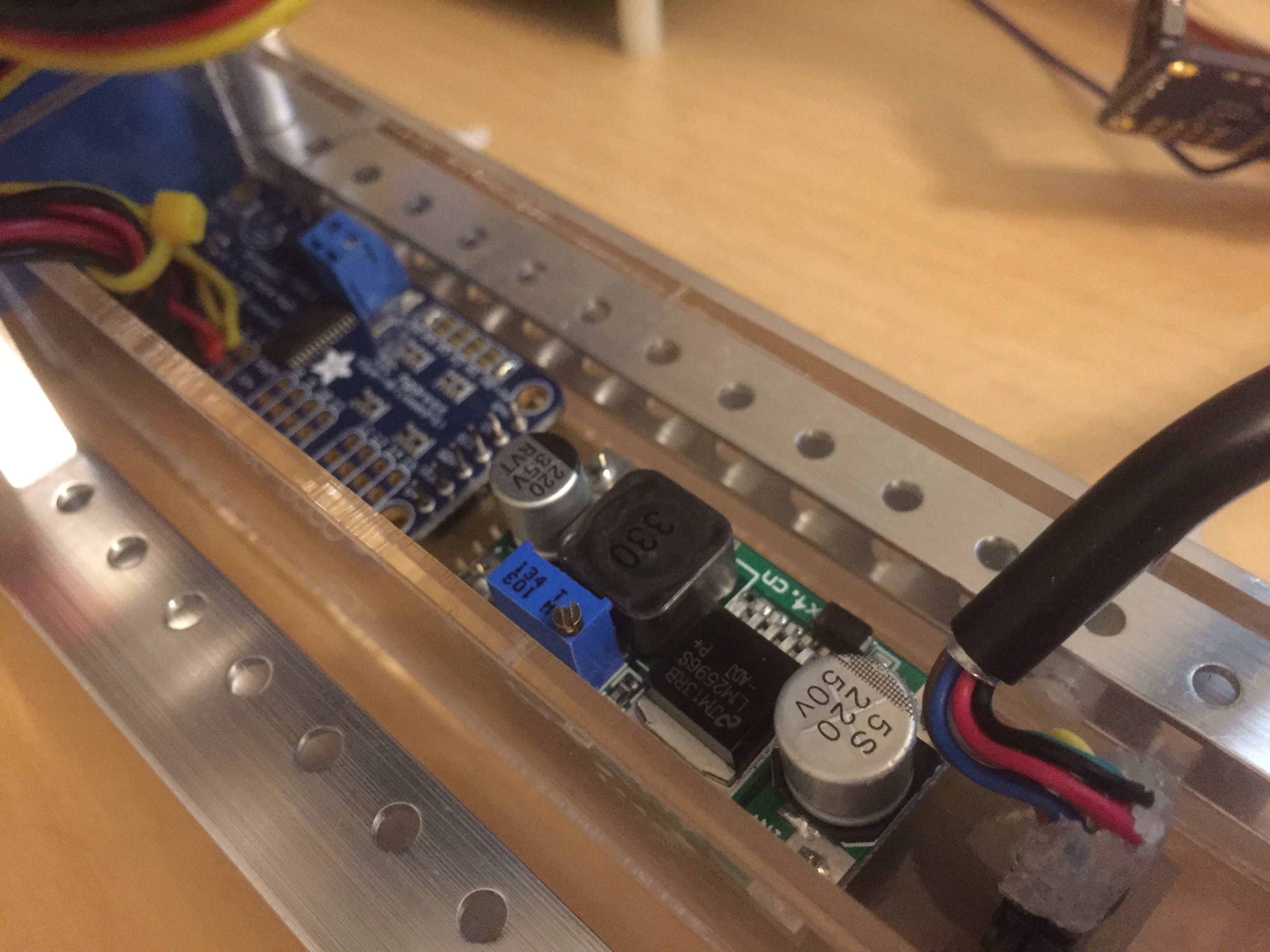
In the above photo, you can see both the two main boards, together with the incoming ROV-BUS connector (bottom right) as well as the servo wiring (top left).
This board is mounted inside a custom cut acrylic box. The box is, in turn, attached to the ROV frame using two nylon bolts. This allows the entire payload to be detached if necessary. To keep the boards water-free, I will eventually pot these components.
Discussions
Become a Hackaday.io Member
Create an account to leave a comment. Already have an account? Log In.