 Eric Hertz
Acquired a bunch of TDA7490 Class-D audio-amplifiers from The Electronic Goldmine for a great price a while back with the intention of trying them out as DC-motor drivers...
A bit ridiculous, but who knows.
Now I'm in need of a semi-permanent DC-motor driver for another project, and so-far all my latest are merely breadboarded, so I thought I'd try it out.
A few things:
- The pin-spacing is smaller than .1in (or even .05in), I managed to bend one out to two rows of .1in spacing, but it's quite a stretch. The second one is three rows.
- It requires a split-supply... +-10V to +-25V, so I figure I'll use two old laptop power-supplies at 19V 3.5A apiece, removing their mutual connection to earth-ground.
- It can do either two channels (stereo) WRT ground (single-ended) at 25W apiece, or one channel in Bridge-Tied-Load mode at 50W. My original intention was to use BTL, since that'd make for an H-Bridge, but now I don't see that that's necessary. Since it's split-supply, a single half-bridge and "Locked-Antiphase PWM" should do the job, right? Also calculated that the motor's using right around 24W at 12V, and don't really intend on using it much beyond that, so with PWM, single-ended should do the job.
- It takes in *analog*, obviously... I figure I'll use a uC PWM pin, and a low-pass R/C filter.
- Its input is most-likely +-, and calculated (from the reported gain) to be around 1V p-p (typical audio line-level, right?), so I figure I'll use a couple voltage-dividers in series. The first will bring it down from 0-3.6V to something like 0-2V, the second will be attached to the negative-rail, so it'll pull that 0-1V to something more like -0.75-+0.75V. I haven't really done the math, except as a proof-of-concept, since I don't *really* know the input-specs of the amplifier. I'll probably just throw in two potentiometers, one for scaling, the other for offset.
- It's designed for *AC* input... (via AC-coupling capacitor). This is one of the more-questionable aspects... Who knows what its "0" bias-point is...? Is it *actually* at 0V? MAYBE: since I'm planning to use less than its maximum output-power (12V of 19V -> 63%) and since I'm planning to use locked-antiphase (50%PWM duty-cycle = 0 power -> 63%power -> ~80%PWM duty-cycle?)... and *maybe* the thing can actually respond to higher-than-audible frequency-inputs (it has ~200kHz PWM output!)... Then *maybe* I can get away with directly inputting the uC's PWM and plausibly even disregard the gain in-hardware, send it "rail-to-rail"... hmmm (new idea, as of this writing).
- It uses a *lot* of support-circuitry compared to most dedicated motor-H-Bridge chips, including *several* R/C filters, and L/C filters as well.... Nevermind *4* 2200uF 25V capacitors (large!).
There's probably more I'm forgetting...
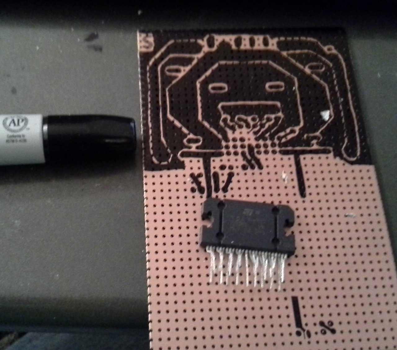
Either way, that last bullet-point is a bit annoying as far as using this chip as a motor driver in *several* projects... This'll probably end up being a one-off. So I decided that even if this doesn't work as a motor-driver, I could make use of it as a... *cough* audio-amplifier *cough*. So I decided to make a somewhat general-purpose board for experimenting that'll also be usable as it was intended.
The beginnings of which are shown in the image, above...
I usually do point-to-point hand-wiring for one-off things like this, ("infinite" layers for "traces"!), but I'm running low on solderable-breadboard of that size... And this'll be somewhat permanent one way or another, so why not try my hand at PCB-etching again (it's been over a decade!). I haven't any laser-printer toner in my possession, and my laser isn't yet attached to a reliable 2-axis system (seriously, @johnowhitaker figured out how to laser(verb) toner directly onto a PCB, brilliant, and definitely in my TODOs once I have my 2-axis system running!). and I don't have a laser-printer for toner-transferring, so I'm trying the "old" method of PCB-etching... traces drawn by-hand.
I tried to hand-draw the thing on paper before laying it out, but it's a little bit difficult for several reasons, so I ended up drawing it in a regular ol' PCB program (gEDA PCB)...

This layout is *highly* derived from the example in the datasheet, but of course modified for my multi-purpose experiments, and a few other things.
The Copper-Clad board I decided to use is *pre-drilled* at .1in spacing, so that's kinda handy and kinda not. It definitely makes layout a bit more complicated... Nevermind all the pins needing to be .1in (which, again, the chip isn't), there's also a bit of work to be done to assure that traces don't go through holes and get cut in the process. A few other things, as well... Also some consideration as to how to solder on both-sides things that mount right-atop the board, like the big-ass capacitors and the terminal-blocks (as opposed to having leads that stick a little above it, like resistors and ceramic-caps).
This project would've been done several days ago if I'da done it point-to-point on a breadboard. But now I'm *finally* on to transferring (by hand) from the PCB-layout in software to the copper-clad board (again, shown in the first picture).
Some of the really skinny traces and traces-between-pads will be difficult with a permanent-marker, but I long-ago acquired a bunch of stuff from a robo-hacker friend who went guitarist, including a bunch of these press-on/rub-on "dry transfers" from RadioShack that should handle the really tight spots.
The latest delay is that my permanent-marker-traces bridged a little bit in a few places, and I accidentally drew a crossover of one trace, so I need to figure out how to clean those up... worst-case-scenario I'll etch then fix it up with a razor-knife or dremmel, but I'd like to clear it up before etching (I figure there'll probably be a few non-pen-related issues in the etching-process, anyhow... better to alleviate as many as possible from the start!)... So I'm thinking either a cotton-swab and some alcohol, or maybe a toothpick... both of which might just result in spreading it 'round. Alternatively, maybe just *scrape* the ink off those areas...
This was supposed to be finished *days* ago... the project I'm doing this for has been in-the-works and thus non-functional for far too long!
(The project this is for is the first axis of a large modular 3-axis system... hopefully usable for several purposes including a lathe, a mill, a [PCB] router, laser-table, and (with this first axis) a drill-press, The mechanics of the first axis are functional. The "drill-press" idea includes a second motor which will be used-as/attached-to the lever... A feedback-loop between the two motors (and encoders) will, hopefully, allow for force-feedback despite the significant gearing-down of the axis-motor. Another new experiment...
Discussions
Become a Hackaday.io Member
Create an account to leave a comment. Already have an account? Log In.
your PCB layout reminds me of space invaders and that makes me happy.
also i bought an LM3886 something like... i dunno, 15 years ago, with the intention of building an amplifier of some kind. Never happened. Yours if you want it.
Are you sure? yes | no
I actually built ghetto amplifiers modules into heatsink with those LM3886. :)
Are you sure? yes | no
Hah, thanks! I thought Space-Invaders, too :) Happy coincidence, and surely a lot stole from the ST design. Not *intended* on my part :)
I think I'm stocked on audio-amps for now, still have four of these TDAs! But thanks for the offer! But, whoa! That looks a heck of a lot easier to work with... and much more thorough documentation... Build It!
Just finished etching, bouts to clean up
Are you sure? yes | no
Take a look at the left half of the instrumentation amplifier (just before the R1/R3 and the rest of the differential amplifier which is connected to the speaker). The BTL amplifier is wired up the same way with V2 = Gnd.
http://masteringelectronicsdesign.com/how-to-derive-the-instrumentation-amplifier-transfer-function/
They explain how the circuit works much better than I can type.
Are you sure? yes | no
Cool thanks. I'd looked around for BTL circuits (many of which look quite similar) but I hadn't thought to look for an instrumentation-amp.
Are you sure? yes | no
Me neither until I was typing up the reply trying to explain it with inverting amplifier, then I noticed the symmetry and instrumentation amp came to mind. Now it makes sense.
Are you sure? yes | no
great observation!
Are you sure? yes | no
TBH, that page has much too much math for my taste... so I did some analysis of my own from the image you linked (thanks for that). Some interesting results: It looks like the output voltage of the lower op-amp will, in fact, be slightly lower in absolute-value than the upper op-amp's output... which means the "bridged" output will not be centered at zero. (IG goes through R55 and RG for the upper-output, but only through R6 for the lower-output). Not a big deal, but an interesting observation.
I think that also means that adjusting the gain changes *something* at which "clipping" occurs... I haven't fully wrapped my head around it, but something like in a normal op-amp circuit, clipping occurs at input * gain = V+, whereas in this circuit it's something more like input * gain^2 = V+ (or something). Again, not particularly relevent, but another interesting observation.
Similarly-interesting-but-unrelated: It looks (again, to me) like adjusting the voltage input to the second op-amp (e.g. setting it to 1V rather than 0V) has the effect of adjusting the *gain* of the circuit. This I find quite interesting, as it basically means all those 2-potentiometeres-in-one used for headphone-amplifiers, stereos, and whatnot could be replaced with a single potentiometer, using this circuit... Or, even more interesting, a *voltage-controlled gain* could be controlled by e.g. a uC PWM output. Cool! Another case where this intrigues me is e.g. this old Jukebox Amplifier I've got sitting-around which has a volume-control which A) only uses one potentiometer for stereo, and B) has a *delayed* change-in-volume, as though its volume potentiometer is connected to a capacitor. (which could be done with a voltage-controlled-gain circuit, but not with a typical input-voltage-divider-controlled-gain/op-amp circuit). I wondered how it worked, and this might well explain that. Besides making for a nicely-ramped volume-adjustment, this also serves to basically elliminate noise from a dirty potentiometer (excellent), as changes on the potentiometer's output is essentially "debounced". Very cool, and something I might just have to add to my Marantz stereo if/when I ever hack it.
I remember learning about instrumentation-amps in school, but I don't remember those observations. Thanks for commenting with this!
Are you sure? yes | no
This is the droid that you are looking for: V12 = -V11 * R6/(R5+RG)
(dark equation on my browser because of transparent background.)
So to make them symmetrical around 0V, i.e. V12 = -V11,
it follows that R6 = (R5+RG). So for R5 = R6, RG=0
I have no idea what the actual circuit would do without doing a simulation, but that's what the math says.
Are you sure? yes | no
One of the "multipurpose/experimental" add-ons was an option to directly-connect potentiometer-voltage-dividers to the inputs... If this works, when the POT's at 50%, the motor shouldn't move, when it's at 0% it should be full-speed reverse, and 100% would be full-speed forward...
In a sense, this amplifier-chip could be used pretty easily for standalone motor speed-control. It also has some feedback pins, which, now that I think about it, could plausibly be wired-up to some sort of speed/position sensor...
It seems almost plausible to create something almost exactly like a high-power R/C servo with little more than this chip, its support-components, and a potentiometer attached to the motor-shaft... Hmmm... The majority of the circuit analog, but the output with the benefits of PWM... interesting.
Are you sure? yes | no
I am pretty sure that the "0" bias point is at the gnd level.
In fig 3 for the BTL connection, one of the channel has the preamp input connected to ground. So if the bias point wasn't at gnd, then the offset would be amplified.
Are you sure? yes | no
One would think... but since you've looked that far, maybe you'd be interested in another curiosity of BTL mode... The feedbacks are connected... So, imagine a case where the input signal causes that output to "rail" positive... Logically, if the output is "more positive" than GND (on the second input), then the second output will go negative to compensate, right...? Except there's a voltage-divider in question, and the voltage divided into the second amplifier is *inherently* lower than ground... (52.3k+4.7k up top, but only 52.3k below), so then the second output will go positive again... which means the output won't be centered at ground, but will, in fact, have an offset toward positive...
Are you sure? yes | no
Looks Like!
Are you sure? yes | no