Edit : this exploratory page is interesting but not the final word. The rest is logged at More bistables...
You know that a MUX can be easily turned into a latch by looping the output back to one input...
And in From XOR to MUX I turn a XOR into a MUX. So the next logical step is to connect the output to one of the inputs...
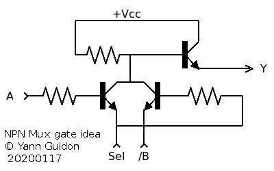
The natural choice is to connect Y to A because the polarities are compatible.
This is unfair for the /B input which is inverted and requires a pull-down transistor.
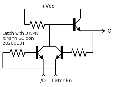
My quest is to make a D-FlipFlop circuit with the least number of bipolar transistors. A pair of latches will require another NPN to pull /D low, but another topology is possible if complementary transistors are allowed :-) As in the early IBM ECL circuits (Current Steering Logic) I can make the next stage complementary to save one transistor... As a bonus, there is no need of a complementary clock signal and the output data has recovered its original polarity :-D
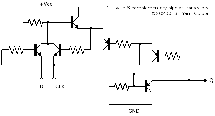
Now, the more I look at it, the more I doubt it can work as is. There must be errors here and there...
I'm sure the CLK signal will create quite a lot of problems and it must be split into overlapped, out-of-phase signals (2-phase clock ?)
But I'll have to test and you know, you're never safe from a good surprise... who knows if it could be the basis of a new clock or UART ?
Edit :
@roelh commented :
- Normally, both transistors must invert the signal, but in your circuit one of them is an emitter follower that does not invert.
"yes but" double inversion is not the real requirement for latching, it's a consequence that transistors can only invert. We can apply the https://en.wikipedia.org/wiki/Barkhausen_stability_criterion which states : gain > 1 and phase = 0 (mod 2Pi). To fulfill this condition, you need 2 transistors because each adds a phase of Pi, and their gain is >1. However, most latches are used both in common emitter configuration, which creates the double inversion. Here I use another structure, similar to a SCR https://en.wikipedia.org/wiki/Thyristor
 "It acts exclusively as a bistable switch, conducting when the gate receives a current trigger, and continuing to conduct until the voltage across the device is reversed biased, or until the voltage is removed" because I use the common collector output (borrowed from the classic ECL gates structures). My circuit is almost identical, I only added a base resistor to prevent damage and too hard a saturation. The phase is 0 and the gain is very high so latching should occur as long as the CLK level is enough (which will be another concern for later)
- Personally I would design a transistor CPU in such a way that the registers are latches (that was also done by Dieter in his transistor CPU).
I agree too : this cuts the transistor count in half and this is what is intended for #YGREC8.
However it is necessary to see the full DFF working on the bench and be familiar with its idiosynchrasies, before I cut it in half. It's important because I'll have to decide which part is NPN and which part is PNP. Apparently here the first/common latch is PNP because there are fewer transistors, and the bulk (replicated for each register) would be NPN because I have more of these.
The speed and timing of the circuit will depend on the power supply, the saturation and other parameters... I might have to add a anti-saturation diode in the SCR latch part, while the saturation of the emitter might not be such a problem. In fact, saturation is often considered in common emitter configurations, but here the emitter is a data input so I'm in a totally uncharted territory...
And I would love to test the circuit in both Silicon and Germanium versions. I don't have Germanium NPN transistors though (or so few, eventually) so it would be interesting to find a solution with only a single type/polarity.
Time to play with Falstad !!!
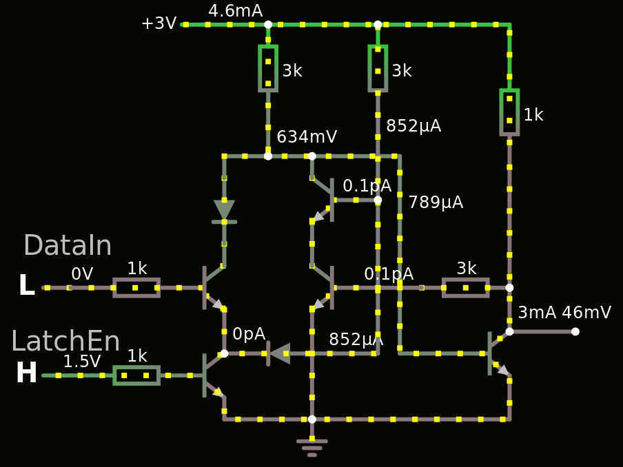
So I played with Falstad for hours and came up with this simulation :
The code :
$ 1 0.000005 0.11813604128656459 59 5 43
w 256 112 304 112 1
r 304 112 304 176 0 3000
t 240 304 272 304 0 1 -0.6341321488431279 -0.028103041567142044 100
t 368 240 336 240 0 1 -0.1887122097919851 0.04999867754124937 100
t 368 304 336 304 0 1 -0.34921107400413387 0.046210209898701 100
r 384 112 384 176 0 3000
r 176 304 240 304 0 1000
w 304 176 304 208 2
w 272 288 272 272 0
w 272 208 304 208 0
w 304 208 336 208 0
w 336 208 336 224 0
w 336 288 336 256 0
L 160 304 128 304 0 0 false 1.53 0
L 160 368 128 368 0 1 false 1.53 0
w 272 352 272 320 1
w 352 352 384 352 1
w 384 240 384 352 0
t 240 368 272 368 0 1 0.5923557570386799 0.6204587987064846 100
w 304 112 384 112 0
w 384 192 384 176 1
w 272 400 272 384 0
w 400 208 336 208 0
r 176 368 240 368 0 1000
t 400 352 480 352 0 1 0.5879219616224369 0.6341321712360694 100
w 384 112 480 112 0
w 480 240 480 304 0
r 480 112 480 240 0 1000
w 480 336 528 336 0
w 400 208 400 272 1
w 480 368 480 400 0
x 125 280 191 283 4 20 DataIn
x 116 350 197 353 4 20 LatchEn
w 480 336 480 304 3
r 416 304 480 304 0 3000
d 272 224 272 272 2 1N5711
w 272 208 272 224 0
d 352 352 272 352 2 1N5711
w 384 192 384 240 0
w 400 272 400 352 0
w 368 304 416 304 1
w 160 304 176 304 2
w 160 368 176 368 2
w 368 240 384 240 1
w 480 400 336 400 0
w 272 400 336 400 0
w 336 320 336 400 0
g 336 400 336 416 0
R 256 112 224 112 0 0 40 3 0 0 0.5
38 13 2 0 3 A\sLow
38 13 1 0 3 A\sHigh
38 14 2 0 3 CLK\slow
38 14 1 0 3 CLK\shigh
Note that the diodes are not standard, but low-drop Schottky, or else the bases can't be pulled down low enough. Or else another diode must be added to the output transistor's base...
I've also had strange problems with the inputs going all the way up to 3V. This seems to be solved with the 0-1.5V range but this needs to be explored and explained.
Thanks again to @roelh for pointing my errors ;-)
There are still a lot of things to examine, for example if it's topologically equivalent to other circuits, and what the advantages & drawbacks are. One great part is the Latch Enable signal and transistor that can be shared with other cells, so there are 4 transistors that matter, and most cells also have 4 transistors (IIRC).
I've been able to make a full D-FlipFlop :
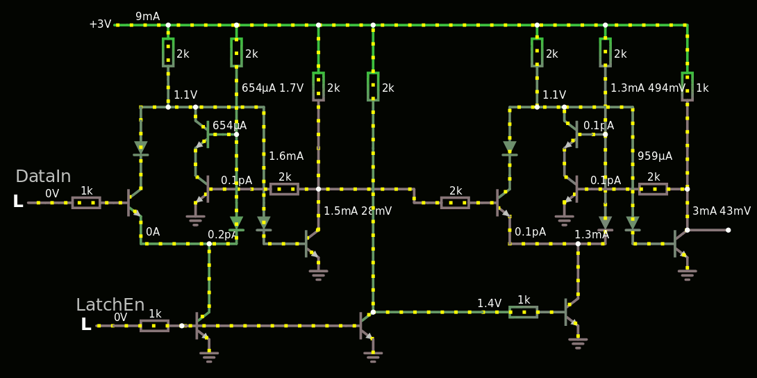
This version uses all-silicon standard parts, because I added a diode to the output's base.
From there I could build a shift register, which opens the door to Johnson counters, LFSRs, UARTs...
And here is a first attempt at a divide-by-two cell:
I had convergence problems and added a couple of 10M resistors.
I suspect there are 2 superfluous transistors to link the right latch back to the left...
In the end I chose a different method, that draws 2× less current and uses fewer parts.
 Yann Guidon / YGDES
Discussions
Become a Hackaday.io Member
Create an account to leave a comment. Already have an account? Log In.
Hi Yann, the feedback of your latch has the wrong polarity. Normally, both transistors must invert the signal, but in your circuit one of them is an emitter follower that does not invert. Personally I would design a transistor CPU in such a way that the registers are latches (that was alsao done by Dieter in his transistor CPU).
Are you sure? yes | no
I hope my update covers your concerns :-)
I'll see/know/understand better with a few Falstad simulations and some workbench time...
Are you sure? yes | no
Both transistors in SCR configuration work, because the output comes from the collector, that has pi phase difference with the base. But in your configuration, you take the output from the emitter, that has the same phase as the base. Try it in Falstad !
Are you sure? yes | no
Indeed I'm trying it in Falstad and it latches :-)
OK I have some funny unexpected behaviour but the latch is there.
Will update soon :-)
___________________________
OK the latch is "weird" and it looks more like a MUX than a latch...
Are you sure? yes | no
I owe @roelh an apology : it seems I have mistaken the SCR topology with the 2-transistors current limiter.
yeah I should return to bed ;-)
Are you sure? yes | no
Perhaps this will earn me a position in the Hackaday TTL-ers team ?
Are you sure? yes | no
What sort of position ? :-D
Are you sure? yes | no
The Hackaday-TTLers page shows a team of 36 persons. I wondered what I have to do to get in that list... But I wouldn't say no to a payed position ;)
Are you sure? yes | no
wait, you're not a TTLer yet ??? :-O
Are you sure? yes | no