 Jose Ignacio Romero
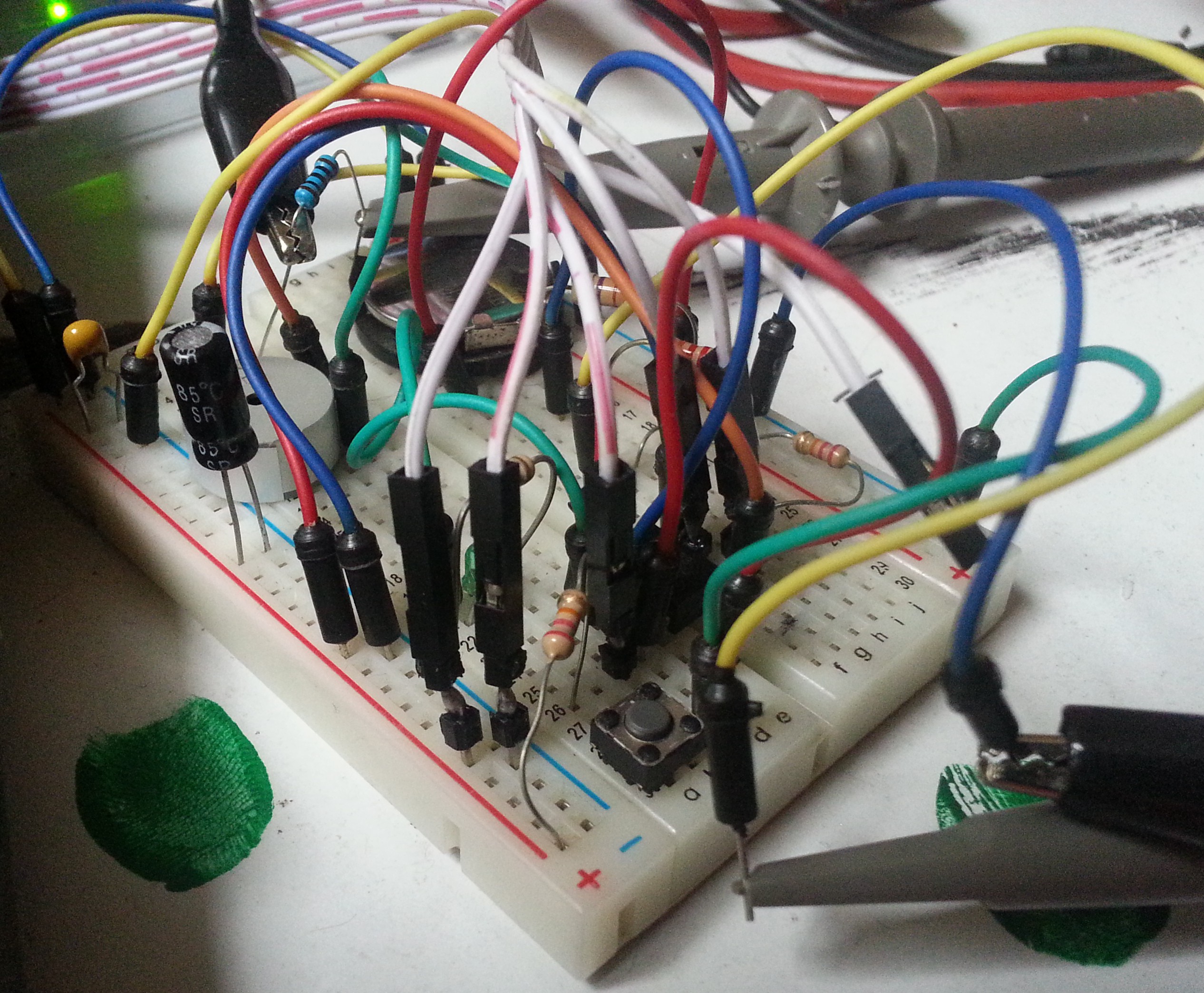
To get the principles right before making PCBs I worked on a breadboard prototype using a PIC12F683 as the main processor, by using the slowest internal clock and sleep modes I managed to keep system-wide power consumption around 1µA while "off", 200µA when idle, and less than half a milliamp while beeping.
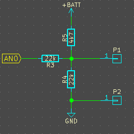
This is the schematic, not shown are a 100Ω resistor and extra capacitance used to measure power consumption (can be seen in the back of the breadboard, hooked up to the probe.)
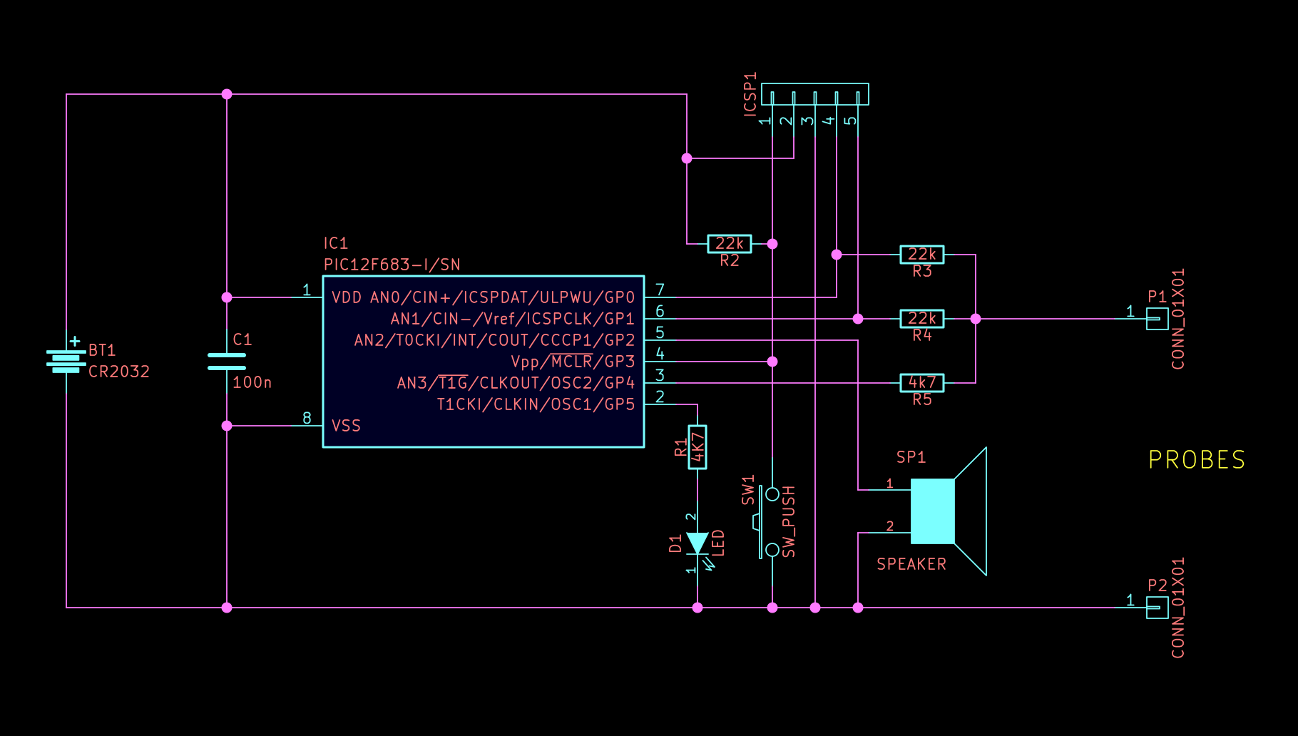
The heart of the tester is the circuit formed by the GPIO pins GP0, GP1 and GP4, and resistors R3, R4 and R5. The PIC controls them to create 3 different circuit configurations:
Sleep Mode
When the micro is asleep, that circuit is configured as follows:
GP0 and GP1 are set HIGH, and GP4 is left as a digital input with interrupt on change set up right before entering sleep mode. Since all 3 pin potentials are at the positive battery voltage, there is no current flowing, leaving only parasitic leakage currents as the main power consumer in the circuit (measured 1-2uA).
Continuity Test Mode
When the user touches the probes, GP4's level changes to LOW, causing the micro to wake up. Once it's up, it switches to the low voltage continuity test mode:
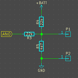 GP1 and GP4 are set as digital outputs, with levels HIGH and LOW respectively. That forms a voltage divider between R4 and R5 which lowers the voltage of probe P1 to around 0.52 volts, just low enough to not disturb silicon diodes significantly. GP0/AN0 is set as an analog input and it's samples around 60 times a second using the built in ADC. When the voltage falls below a preset threshold, the beeper and LED are turned on until the probes read as open again. To help catch short glitches, the beep routine will stretch them to at least 60ms.
Diode Test Mode
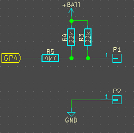
When switched to diode test mode, the resistor configuration (ie., the logic for GP1 and GP4) is swapped, so that there are ~2.5V at the probe:
The analog input is sampled as before, but the beep state will be entered if the voltage at the probe is below a silicon diode junction (<0.7V). Once beeping two things can happen. if the voltage is below a shottky diode junction (<0.1V) it is a short circuit, therefore the beeper will beep indefinitely. On the other hand, if the voltage is within normal parameters, the beep will stop after a short time, but the led will stay on, confirming that the diode is OK. This mode is very useful to check a large amount of diodes by ear in a short time, without looking away from the probes. It is intended to emulate the diode test mode found in some Fluke models like the 179 (a 300 buck multimeter!).
If the tester has been idle for more than a couple minutes, it will return to sleep mode to save power. With the figures I've measured on the breadboard prototype it should give a battery life of over 10 years of stand by, or 800 hours of use (assuming it's beeping 10% of the time), which is fairly reasonable for a single button cell.
Discussions
Become a Hackaday.io Member
Create an account to leave a comment. Already have an account? Log In.