 Jacob Creedon
After the PCB has been assembled and reflowed. It is time to test to make sure there are no shorts or opens. For testing this I opted to do continuity checks on the USB side, and a system check on the audio side.
USB
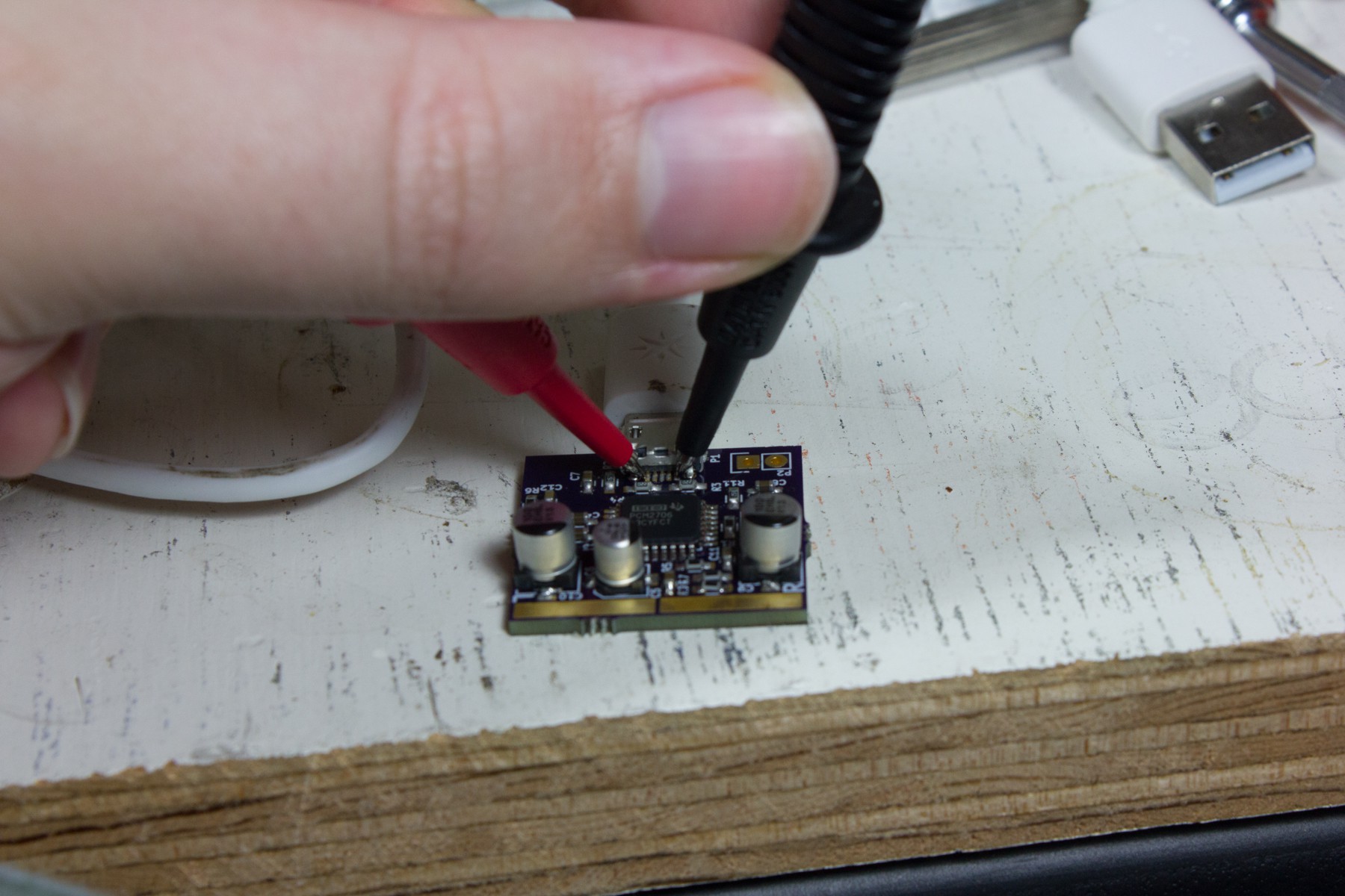
The USB connector was the most tricky to solder because the pins were underneath it, and the most prone to failure. The first step is to make sure there are no shorts between any of the pins. Next make sure that the pins actually reach their corresponding pin on the IC. Finally, make sure that the pins on the connector are not open between it and the cable.
Audio
Once the USB side is tested, we connect it to a computer to test audio output. For this testing I used a Raspberry Pi, so even if I messed something up, ruining a port on a Pi is not as bad as on my main computer. The first check is to see if ALSA picks it up. This can be done by running:
aplay -l
to list connected playback devices.
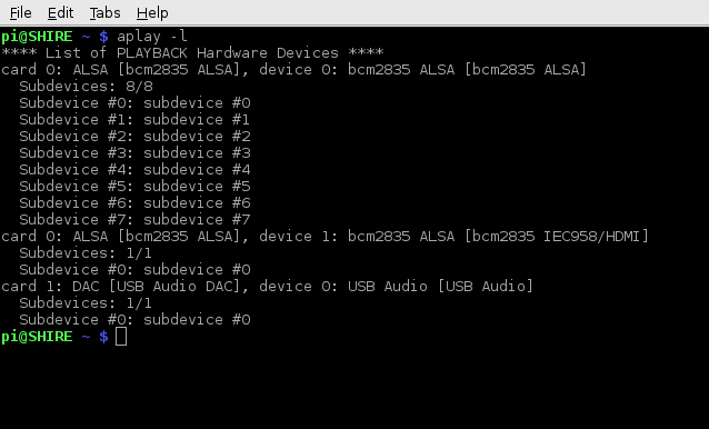
So here we can see the sound card "USB Audi DAC" show up as card 1 subdevice 0. In ALSA this equates to the designation `hw:1,0`. Using that information we can then use `speaker-test` to generate test signals. I used the following command:
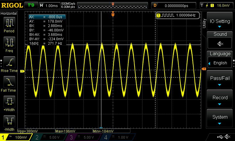
speaker-test -c 2 -f 1000 - t sine -D hw:1,0to generate a 1kHz sine wave on both channels.
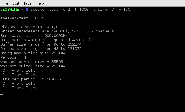
This will alternate that sound on each channel every couple of seconds. We can then probe the pads with an oscilloscope to confirm the output.
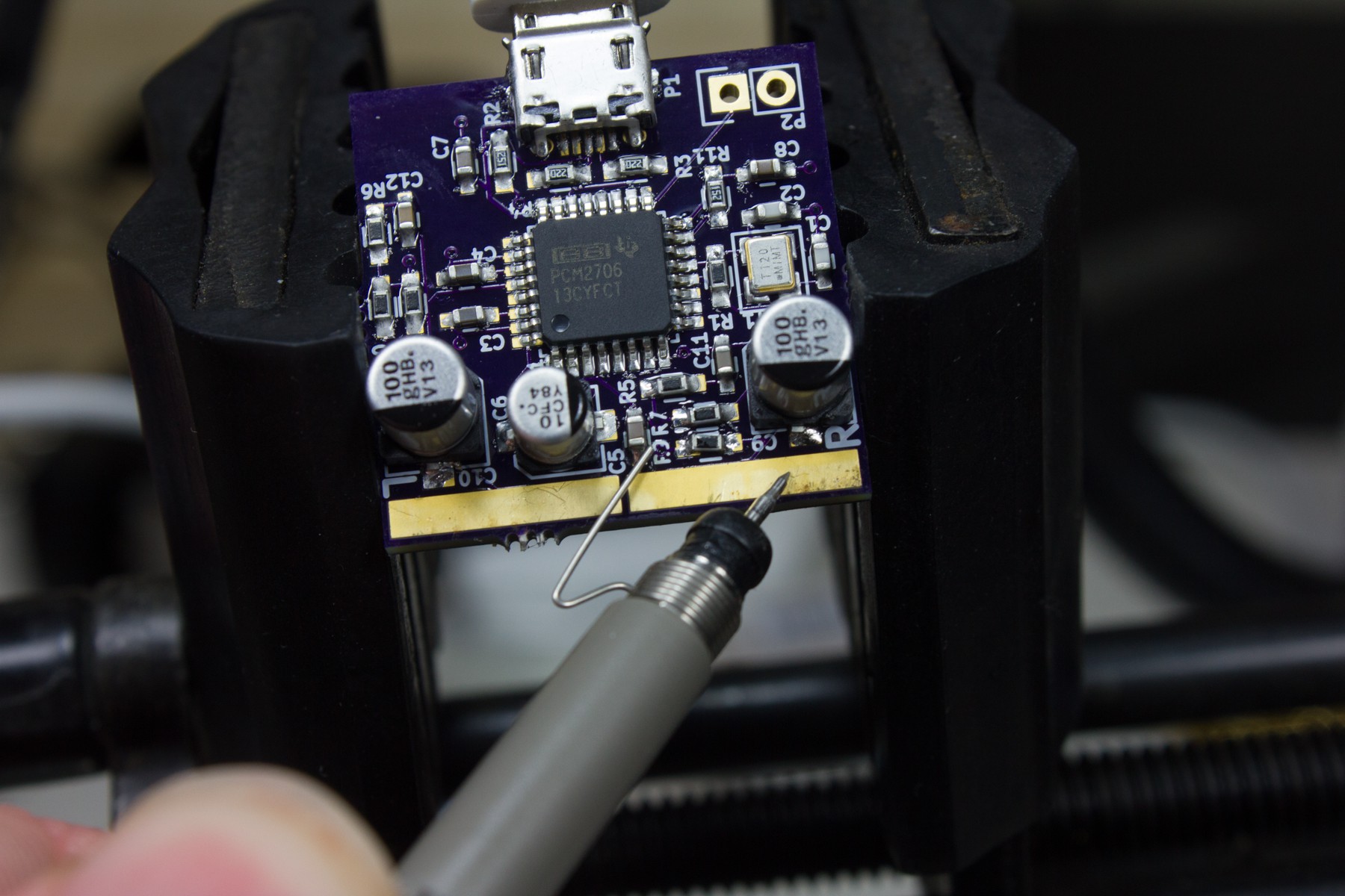
Once both channels are tested and looking good. We are ready to solder on the plugs and connect it to a mixer.
Discussions
Become a Hackaday.io Member
Create an account to leave a comment. Already have an account? Log In.