 Nigel
NigelThe actual hardware needed to create our input stage and the input simulator is fairly simple. We need to buffer/scale, read, and then extract the values coming from our sensor. Since it seems that we only need 1 ADC input with the ability to read 15V we can group 15 of the inputs into one type of circuit, and the
"high" voltage line into another. As most of the sensors the MagiLog will interface with operate at 5V it makes sense for us to set Vref at 5V as well. This means on the 15V input we need to scale that voltage down to fit in a 5V range. We can do this with a simple op amp circuit. Additionally, we need to buffer
our inputs. This will make our device much better at handling nonnominal input voltages. It also has the bonus of providing a high-impedance sink to whatever sensor we are trying to read. This prevents the ADC reading process from affecting the sensor output. To achieve this goal we will use two variations of
the following circuit.
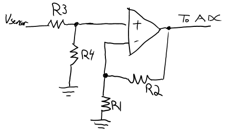
In this circuit the gain of our output is equal to (1+R2/R1)*(R4/(R3+R4)). Depending on what we need to do we can modify values or remove components. We don't need any gain values larger than 1, so this means that we can make the op-amp portion just a voltage follower. To do this we open R1 and short R2, leaving us just with R3 and R4. In the 5V measurement circuit we short R3 and open R4 meaning we don't need any resistors to read 5V signals. For the HV signals we need to scale 15V to 5V and we accomplish this by making R3=2*R4. One thing to note is since I'll probably end up using the 5V rail to power the op-amps I'll need to make sure I use rail-to-rail op-amps. This means that they will be able to output all the way from V- to V+ (Gnd and 5V).
To do the actual reading of the sensor voltage we use an ADC. The one I originally specced out was a TI ADC128S022. It's a standard 5V, 12Bit ADC with 8 input channels. As a quick sanity check we can compare our sample rate to the specifications. With 8 inputs running at 100Hz that gives us a total sample rate of only 800Hz, in other words we have roughly 100x headroom on sampling. This gives us a lot of flexibility to do things like oversample to increase our resolution from 12Bit to 14Bit. Once the data is obtained, it is clocked out with 4-wire SPI. I'll get into the details of this more once I start working on the HDL to interface with the ADC.
To simulate our car conditions I'll like 2 types of outputs. One output will be ~12V with some noise injected to simulate a dirty car power rail. I'm not too sure how I'm going to do this yet so I'll do a part 3 once I get more research in and an idea down on LTspice. The other output will be a oscillating circuit with a Vmax of 0V-5V and a Vmin of 0V. I'll need to find out what sort of time scales I should be simulating so I'll work on that and get it into part 3 as well.
BTW I found that ISO standard I mentioned in the previous log. It's ISO 7637-2.
Discussions
Become a Hackaday.io Member
Create an account to leave a comment. Already have an account? Log In.