 Nigel
NigelOriginally I had planned on having 10 total digital inputs but after doing some more research I think a better configuration will be 12 total inputs with 2 dedicated to tachometer inputs; I'll explain what I mean later in this log. The reason for moving to 12 total is that it fits well with using 2 non-inverting hex buffers as the buffer for the digital in. This will let us accept 5-15V inputs without worrying about blowing anything. As the name suggests, each buffer has 6 inputs and outputs. Unfortunately I only have inverting hex buffers but luckily as our simulator will have a 50% duty cycle we can invert the signal coming in without worry. That said though, for the final MagiLog PCB I'll want to spec out proper non-inverting buffers.
As I learned doing #Honda OBD1 Digital Tachometer some cars have really janky tach signals. Because of this I don't want to commit to trying to accommodate them all in a single circuit. To get around this, the tach inputs will have 3 total pins each. One is the expected data in pin, but we will also include a power and ground line. This lets us put a filter inline with the cable to convert non-square-wave signals to a square-wave we can read easily.
For the simulator we want to be able to simulate a wide range of frequencies with an adjustable Vmax. To do this I've chosen to use a modified version of the 555 timer circuit used to simulate the analog sensor inputs. Note the additional pot and changed threshold capacitor value, and the addition of the recommended decoupling caps.
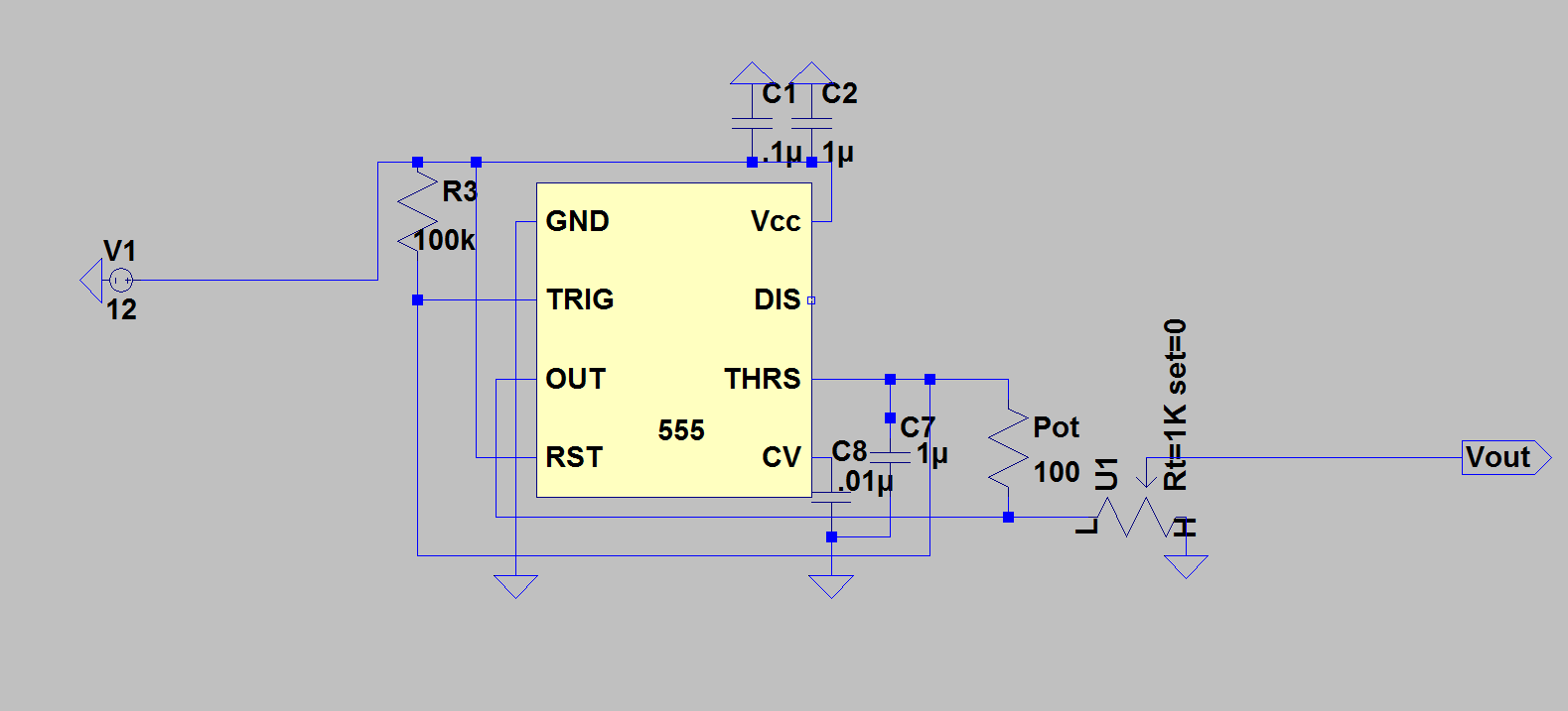
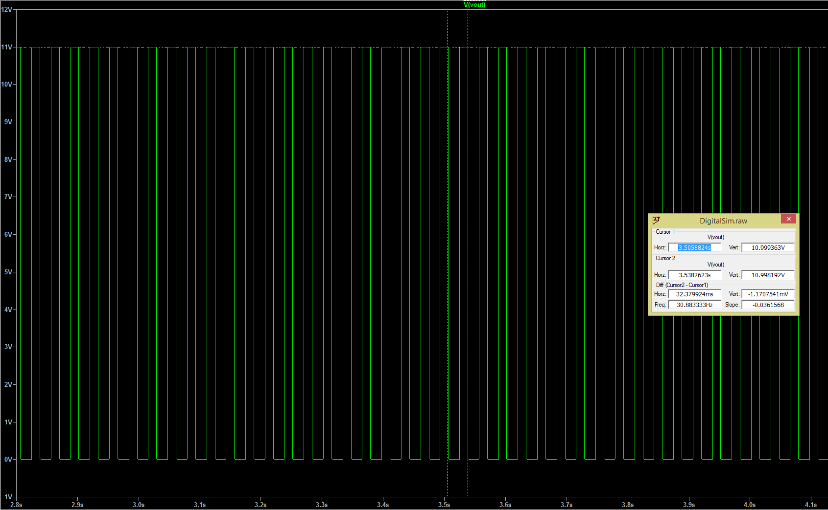
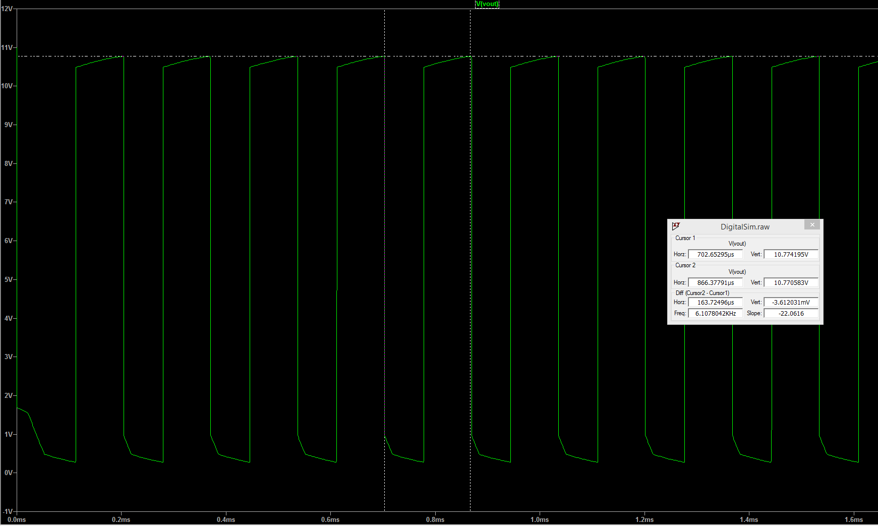
Using this configuration we have full control over the voltage output and we have a usable frequency of around 30Hz-6kHz. Here are the spice outputs.
Slow:
Fast:
Next steps for me will be to get the perf board circuit done and make sure it functions how we expect.
Discussions
Become a Hackaday.io Member
Create an account to leave a comment. Already have an account? Log In.