 Nigel
NigelLast weekend I was able to finish the HDL for digital inputs. The system comprises of 2 modules I’ve written and one pre-built IP. As with the other modules, each word of data will be 16 bits. I’ve chosen the following encoding scheme:
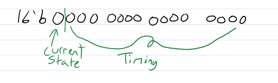
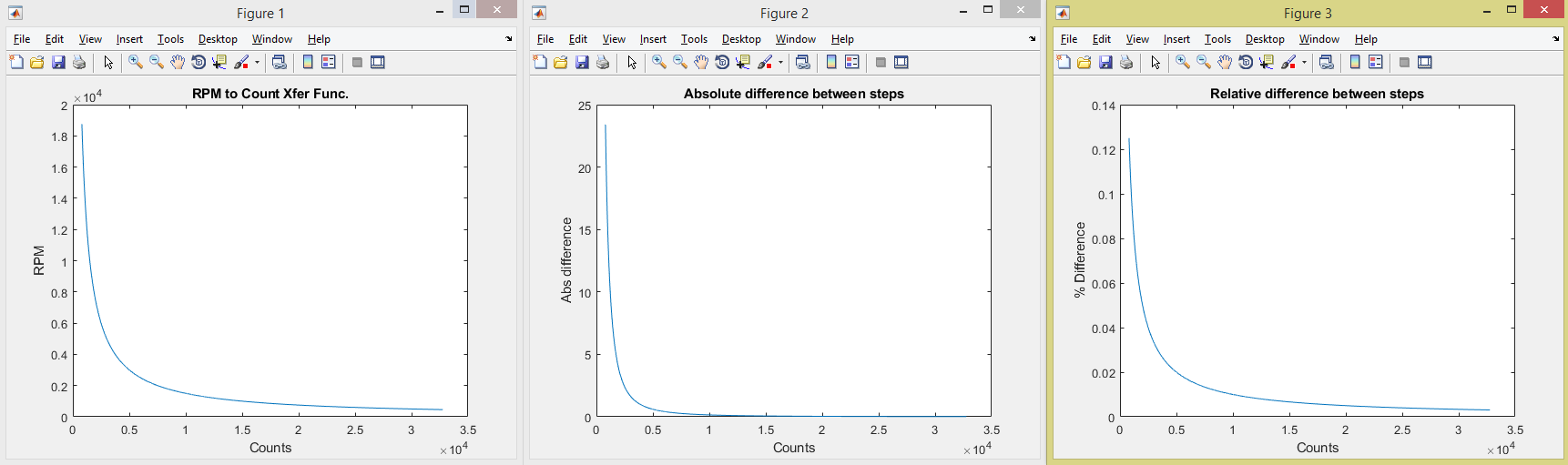
As you can see the MSB is the status bit, it is high when the input is high. The other 15 bits then are left to act as our counter. We won’t be directly calculating frequency/RPM, but the time between pulse events. As this means we need a division step we end up with nonlinearities in the resulting data. As we get closer to a single clock cycle, the read frequency gets very large and the gap between steps also grows. Because of this we need to carefully consider what clock rate we want to use as the timing input. After some playing around I ended up deciding on 250kHz. This gives me a max RPM of 18750 and a minimum of 457.8. The following graphs are cut off at 800 counts for readability. Also, the corresponding frequencies below 800 counts are higher than we probably would ever need.
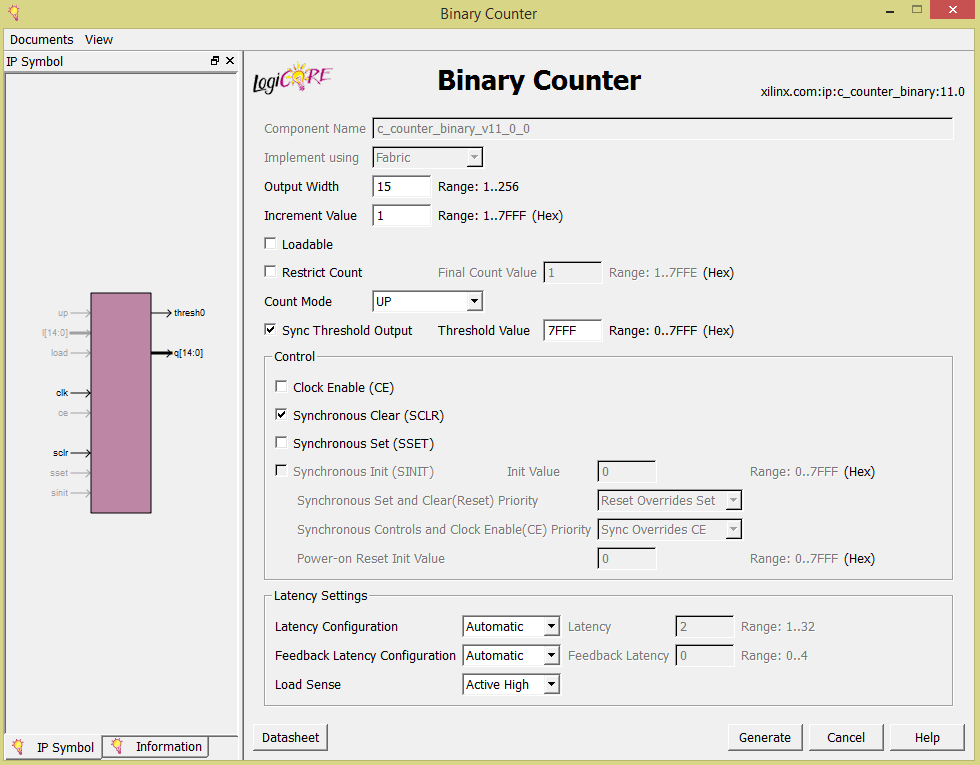
Now onto the actual HDL I’ve used/written. The counter IP is configured as follows.
The digimodule module is the data collector for each channel, it times the gap between pulses and directly connect the pulse state to the state bit. Outside of the timer it’s pretty simple, there’s a one-shot pulse generator to clear the counter and another flag to denote when we’ve hit overflow.
`timescale 1ns / 1ps
//////////////////////////////////////////////////////////////////////////////////
// Company: MagiLog
// Engineer: Nigel Myers
//
// Create Date: 05/17/2018 03:25:31 PM
// Design Name: Digital Input'
// Module Name: DigiModule
// Project Name: MagiLog
// Target Devices:
// Tool Versions:
// Description:
//
// Dependencies:
//
// Revision:
// Revision 0.01 - File Created
// Additional Comments:
//
//////////////////////////////////////////////////////////////////////////////////


    module DigiModule(
    input wire signal, //Module I/O definitions
    input wire clock,
    output wire status,
    output reg [14:0] data
    );

    wire [14:0] q; //Counter output wire
    wire thresh; //Threshold notifier
    wire sclr; //Counter clear
    reg r1, r2, r3; //Single pulse registers
    reg flag; //overflow flag

    c_counter_binary_v11_0_0 DigiCount ( //Counter module
      .clk(clock), // input clk
      .sclr(sclr), // input sclr
      .thresh0(thresh), // output thresh0
      .q(q) // output [14 : 0] q
    );

    assign status = signal; //Continously assign status state to signal level
    assign sclr = r2 && !r3; //Get one pulse out of sclr

    always @(posedge thresh or posedge sclr) begin //Overflow and clear routines
        if (thresh)
            flag = 1'b1;
        else if (sclr)
            flag = 1'b0;
        else
            flag = flag;
    end


    always @(posedge signal) begin //At every signal posedge, we check time since last pulse
        if (flag) begin
            data = 15'b111111111111111; //If data overflowed we use max value as notifier
        end else begin
            data = q;
        end
    end

    always @(posedge clock) begin //Pulse generator for sclr
        r1 <= signal;
        r2 <= r1;
        r3 <= r2;
    end

endmodule
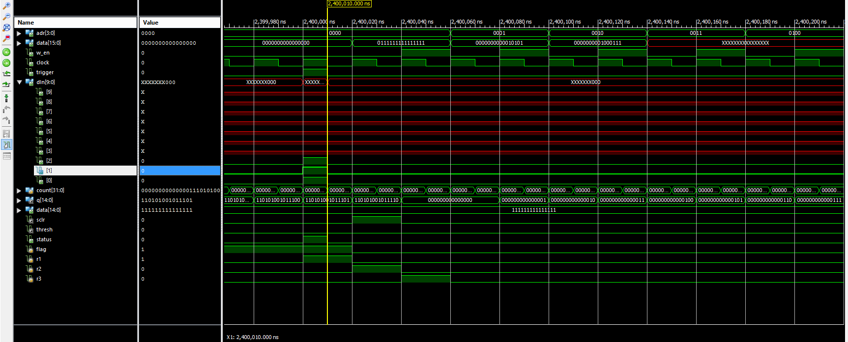
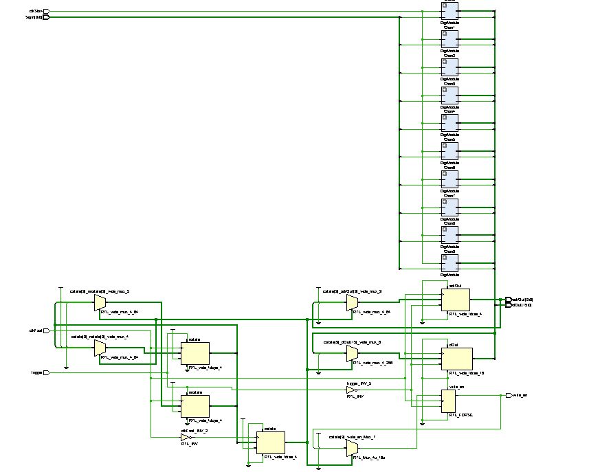
The top-level module consists of a state machine with states for each channel, as well as an idle and send state. During the send state, we set the correct module output and associated address and pulse a write request to SRAM.
module DigitalMaster(
    input wire [9:0] SigIn, //Signals into module
    input wire trigger, clkSlow, clkFast,  //Record trigger, main clock, and timer clock
    output reg [15:0] dOut, //Data output
    output reg [3:0] adrOut, //Output address
    output reg write_en //Ram Write Enable
    );

    wire [15:0] dataMux[9:0]; //Mux for counter module outputs
    reg [3:0] cstate; //State trackers
    reg [3:0] nstate;
    reg [3:0] nnstate;

    localparam [3:0]  //Channel addresses
        Ch0 = 4'b0000,
        Ch1 = 4'b0001,
        Ch2 = 4'b0010,
        Ch3 = 4'b0011,
        Ch4 = 4'b0100,
        Ch5 = 4'b0101,
        Ch6 = 4'b0110,
        Ch7 = 4'b0111,
        Ch8 = 4'b1000,
        Ch9 = 4'b1001,
        Send = 4'b1010,
        Idle = 4'b1011;

    DigiModule Chan0 ( //Instantiate 10 modules
        .signal(SigIn[0]),
        .clock(clkSlow),
        .status(dataMux[0][15]),
        .data(dataMux[0][14:0])
    );
    DigiModule Chan1 (
       .signal(SigIn[1]),
       .clock(clkSlow),
       .status(dataMux[1][15]),
       .data(dataMux[1][14:0])
    );
My next two deliverables are the CAN/OBD simulator PCB and the GPS parsing HDL. Each of these are more difficult than the last so I’m not sure if I’ll be able to keep on schedule. But I’ll try.
Discussions
Become a Hackaday.io Member
Create an account to leave a comment. Already have an account? Log In.