 Bharbour
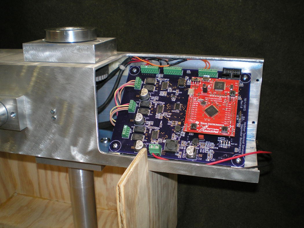
I fabricated the board mounting brackets today, mounted up the PCB and connected enough stuff for testing. Both axes move as expected and the home switches work. The board went in at a 45 degree angle so that it would fit, but what started out as sort of a kludge came out nicely. with the board at an angle like this, it is easier to get to the connectors and generally looks good.
The first thing that I noticed when testing this is that it is noisy when it moves. The DC servo version is much quieter.
I have to machine out holes for the connectors on the end cap that sits next to the board and need to make the cover for the board area. Then it is time to make the antenna mounting arm that goes on the Elevation shaft. There is another motion axis down the center of the antenna mount arm, allowing the antenna to rotate on it's axis to accomodate the polarization shift from the satellite tumbling.
The two small phillips head machine screw heads visible to the left of the circuit board cutout area are the mounting screws for the Azimuth home sensor. The sensor is a photoreflective sensor that looks at the face of the Azimuth drive pulley (visible in the picture next to the board) and senses a hole drilled in the pulley.
The wooden stand shown is necesary because this project will not lie flat on a table in any convenient orientation for working on. In use, the round aluminum tube below the square body will be inserted into the top of a tripod mount and the wooden stand not used.
Discussions
Become a Hackaday.io Member
Create an account to leave a comment. Already have an account? Log In.