 Bharbour
The endcaps for the body tube are done now. one end is just a plug and the other has 3 connectors in it and took quite a bit more machining. A 9 pin D connector (upper one) is the serial data link to control the rotator operation. Power for the system comes in on the lower connector, and a third connector (not visible) behind the circuit board provides the connections for the Theta axis motor on the elevation arm.
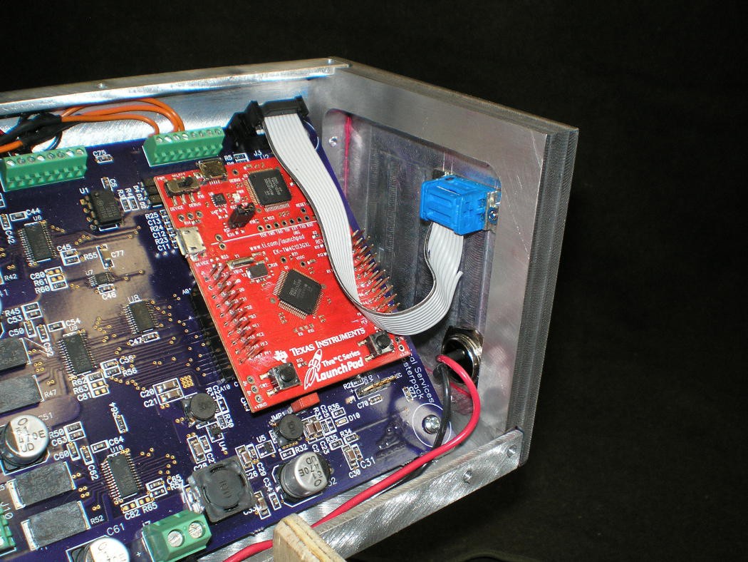
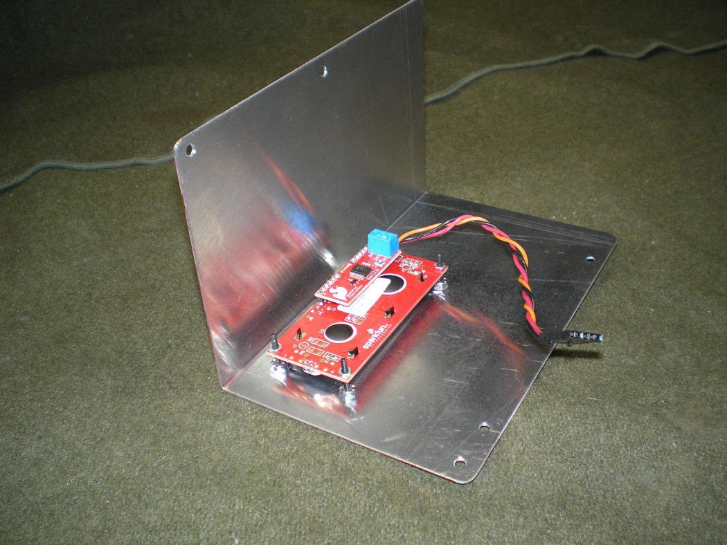
Next, I cut out and folded the cover for the electronics bay. A small LCD (16 characters x 2 lines) is attached to the cover that displays position and status information. In use, the serial link controlling the rotator will be driven by satellite position prediction software (gpredict) that won't show return serial traffic, so I put the LCD in to give some user information back.
This is the rotator with the cover installed:
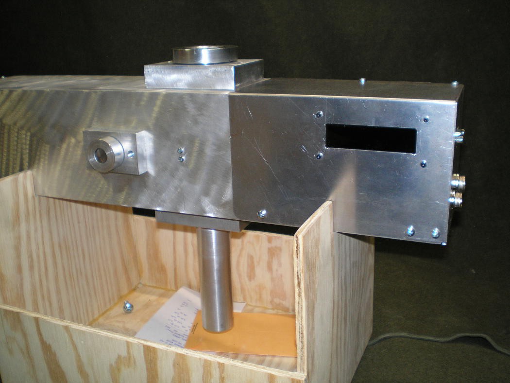
Here is the Elevation Arm mount. A similar disk will be welded to the elevation arm and screws will join the arm to the mount.
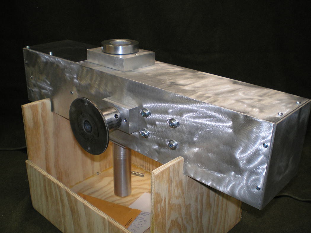
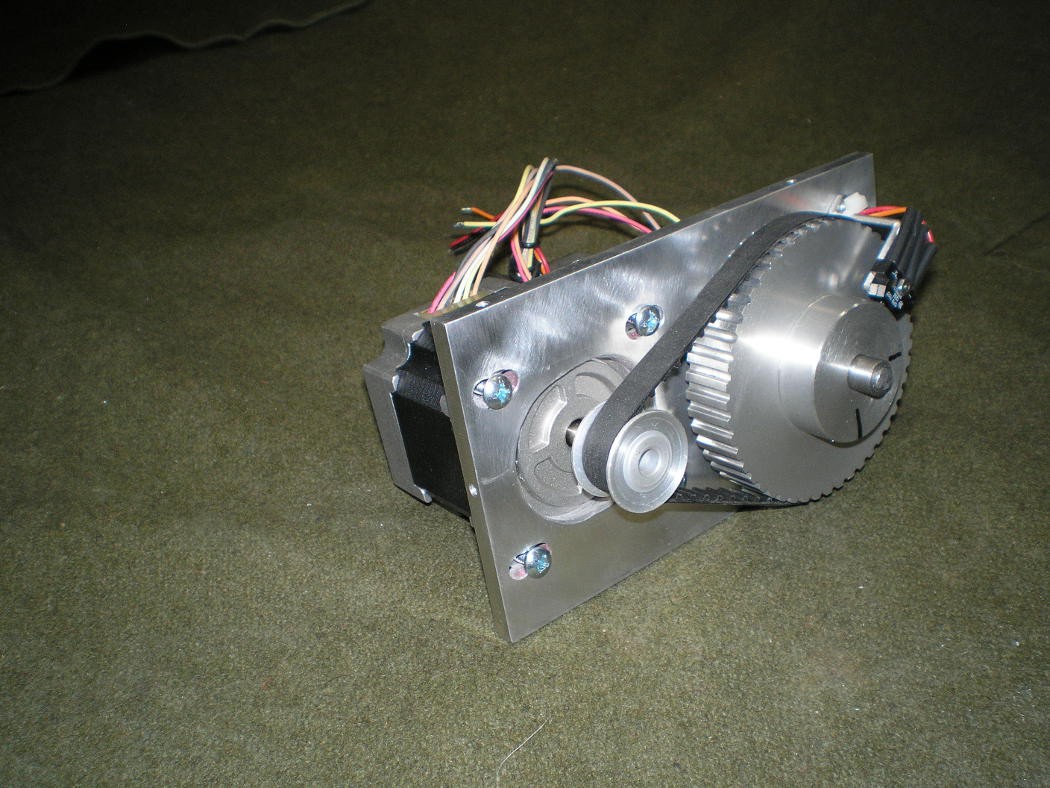
Parts for the Theta axis were the first mechanical things built during the electronics part of the project. I needed a way to Test the home switch operation and the position repeatability for the firmware development. This required mounting the motor, reduction belts and home switch to something, and the Theta axis parts seemed like a good choice.
The short piece of 1" square tubing in this picture is just a mock up of the Theta arm to keep the shaft bearings separated for the software testing. When the I finish the Theta arm, that 1" square tube will be 24" long. A 3" aluminum disk will be welded to the side of the tube for mounting to the rest of the rotator about 1/3 of the way down the tube. It is important that the Theta arm with the antenna attached, balance at the mount plate to keep the Elevation motor loads low.
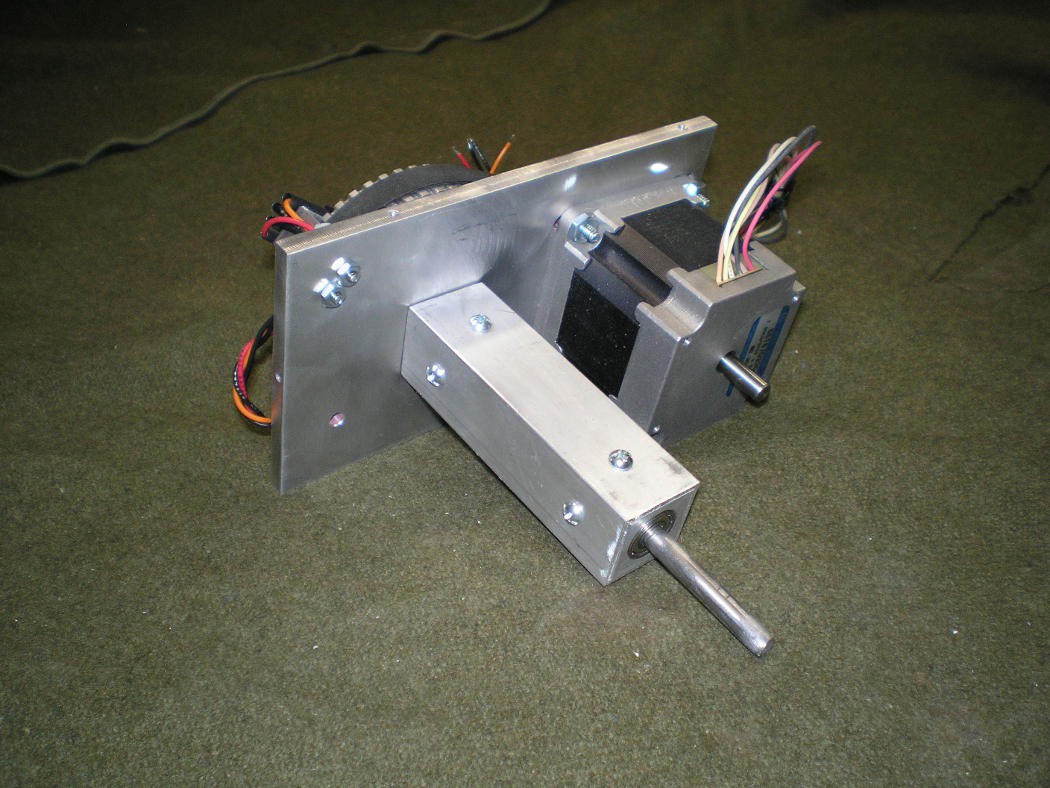
A toothed belt is used to get 4:1 reduction (the same as the other axes) and the home switch is installed. The home switch will probably wind up being re-mounted so that it looks straight down at the face of the pulley and a hole drilled in the pulley. Looking at the set screw holes in the hub of the pulley has a problem, there are 2 holes which could give an incorrect home position if the system were powered up in the wrong initial position.
One of the things that was learned from a previous iteration of these rotators is that adjustment for belt slack is required, even when using toothed belts.
Fabricating the antenna mount, the Theta arm and a cover for the pulley and home sensor will complete the Theta arm build.
Discussions
Become a Hackaday.io Member
Create an account to leave a comment. Already have an account? Log In.