 Moritz Walter
Design specs
Note: these specs have been updated to reflect the current status of the project, while the images in this log are a bit out of date in terms of trace length and other details.
| Power consumption | 500 W (230 V~) or 460 (110 V~) |
| Operation Voltage | 230 V~ (110 V~ over a center tap) |
| Resistance: | 106 Ω |
| Trace length | 400 x 200 mm = 80,000 mm |
| Copper thickness (on PCB) | 1oz aka 1.37 mil aka 35 µm |
| Trace width | 0.37 mm |
It's unclear how the PCBs will actually perform once they're manufacured, but if they're not too much off those parameters, they'll probably work. [Edit: It's not so unclear anymore, see below]
Actual specs (1st batch)
Note: these are the specs of the actually manufactured boards, they differ from the design specs due to manufacturing tolerances and my personal learning curve in this project.
| Power consumption | 420 W (230 V~) or 380 (110 V~) |
| Operation Voltage | 230 V~ (110 V~ over a center tap) |
| Resistance: | 127 Ω |
| Trace length | 400 x 200 mm = 80,000 mm |
| Copper thickness (on PCB) | probably a bit less than 35 µm |
| Trace width | round about 0.37 mm |
Design/Layout
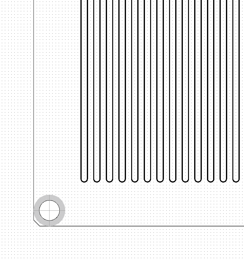
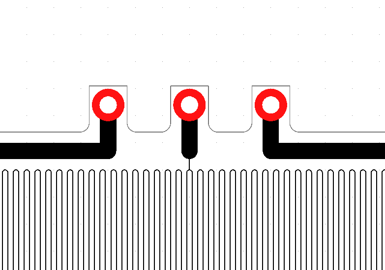
Below you can see the single sided layout of the board. The connectors are meant to be interfacing with M3 cable lugs. I've offset them to be outside of the board, so that shrinking tubes can be used to insolate the connectors once the cable lugs have been attached. The size of the bed is 214x214mm (excluding the terminals) and the center-to-center distance of the mounting holes is 209 mm, so it's compatible with all the MK2 heated bed mounts out there.
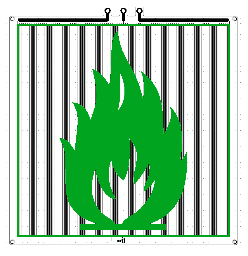
The routing is super simple, just a looooong trance.
The board can be used with 110 V~ by applying the phase to the outer two terminals and neutral to the center terminal. The heat power output for 110 V~ will be a bit lower, about 460 W.
Power Indicator LED
Last but not least, I'm thinking of adding a power indicator LED. It taps into the long trace and takes 10 of the 201 vertical traces, which results in about 12 V voltage differential. I used two 0805 LEDs (one LED for each half wave) to prevent the backward voltage for the non conducting LED blowing it, the third footprint is for a 1kΩ 0805 resistor.
Since these expose hazardous voltages of up to 115 V in normal operation, they have to be sealed using some heat resistant, transparent epoxy or kapton. I'm still not sure if it's worth it to expose the mains traces for the sake of having an indicator light. Since the LED is attached close to the center tap, at least 110 V~ users will not have hazardous voltages on those pads during normal operations.
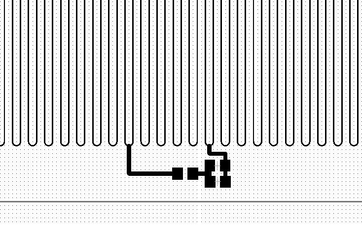
Tapping into the heater trace has the advantage, that the led circuit is not exposed to 230V, thus the current limiting resistor does not have to dissipate so much power. I've also simulated the voltage drop and current for this setup:
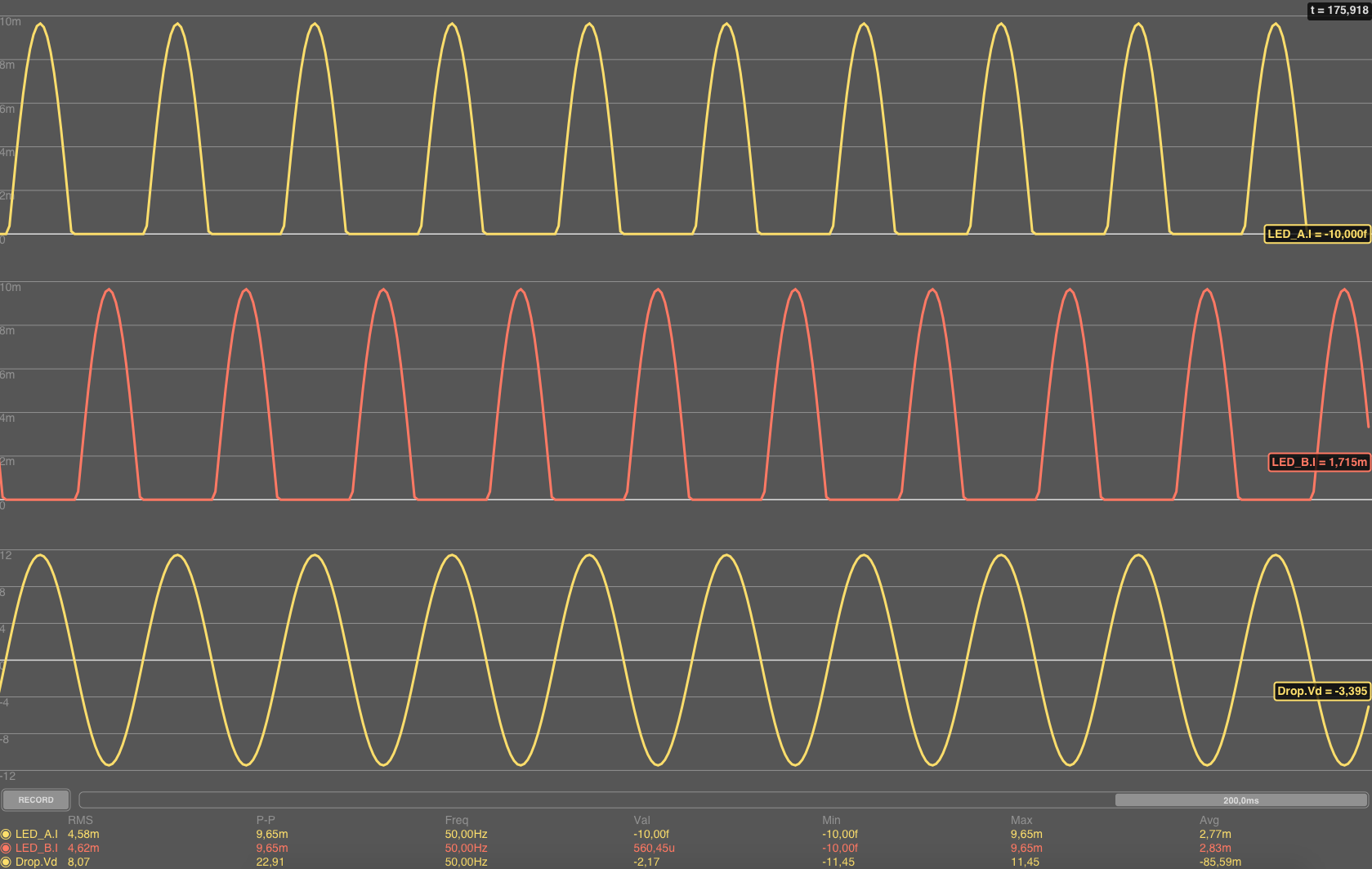
The disadvantage is, that if the heater trace burns through and leaves an open connection point in the section where the LEDs are tapped, the full mains voltage is applied to the LEDs and resistor. The current would still be limited to about 200 mA by the rest of the traces and the resistor, but if the 0805 resistor cannot handle the increased drop of about 210 V, the resistor will burn through and pop right of, so actually, an additional SMD fuse will be required.
RFC
I'm looking forward to get some comments on this, since there are probably some specialists here who can contribute some good ideas (or concerns) to this.
Discussions
Become a Hackaday.io Member
Create an account to leave a comment. Already have an account? Log In.
What if instead of the LED you used a neon indicator lamp, thereby reducing component count? (eg. http://uk.rs-online.com/web/p/neon-indicator-lamps/0105017/)
Would the trade-off of having an additional through hole component be worth it?
Are you sure? yes | no
A neon indicator bulb would work as well and could probably be soldered to the SMD pads. The current limiting resistor and fuse would still be required, so you'd trade in two ~5ct LEDs for one ~20ct bulb. If it's worth it? Probably a matter of taste :)
Are you sure? yes | no
My idea is that the fuse is then not required because of the significantly higher (~90 V) voltage drop, lower operating current, and different failure mode of the bulb. However, I'm not an electrical engineer; please tell me if/why I'm wrong on this.
(BTW, I get your hint that not this question is that of utmost importance regartding this project :) )
Are you sure? yes | no
Neon on power bar switches seems to have a short life of a few years. Do you want to make this trade off?
Are you sure? yes | no