 Moritz Walter
Routing dimension tolerance
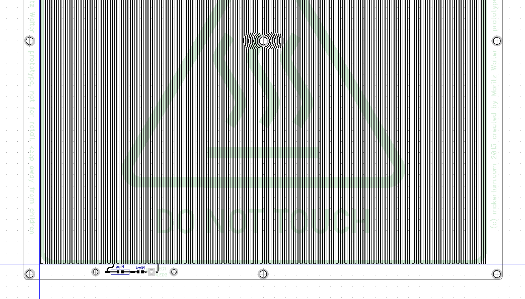
Preparing the manufacturing of the boards, I've noticed that most manufacturers specify a relative trace impedance tolerance of about +-15%. That's a lot, but it's also mostly due to the the absolute routing dimension tolerance of up to 4mil. Since it's mostly due to an absolute error, the effect of it can be minimized by increasing the trace width. In case of the PCB heater, increasing the trace width decreases the trace resistance, which must be compensated by proportionaly increasing the trace length.
Because a double sided heater PCB has additional benefits in tackling thermal deformations within the PCB, I chose to redesign the PCB with double trace width and double trace length, which runs over both sides of the PCB. I could not decrease the gaps between the traces any further, since they're already pretty tight pitched.
Dual voltage
Thinking back and forth if it makes sense to have the board accommodate 230 V and 110 V AC for use in EU and US I came to the conclusion, that there are definitely many more 110 V 3D printers out there than 230 V, so omitting 110 V is not quite an option. However, supporting two voltages on one board blows up the number of necessary connectors from 2 to 5. Those connectors are basically free in the production, but in the installation it means also 3 additional cable lugs, copper screws/nuts and a bridging wire. However, the 5 connector solution also allows the thermal fuse to be omitted in experimental configurations. The pads and connectors of the thermal fuse can then be used to wire the thermistor. It also might be easier to find some beta testers for the board with dual voltage support, so I'll just make the first batch dual voltage and see how it goes from there.
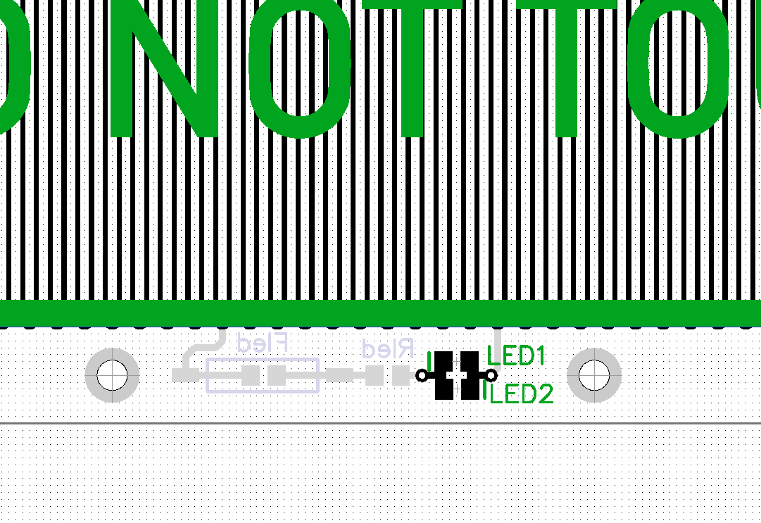
LED fuse and plastic cover mount
The led has now a fuse mounted to the back side and two mounting holes for a transparent protective plastic cover to be mounted over the components.
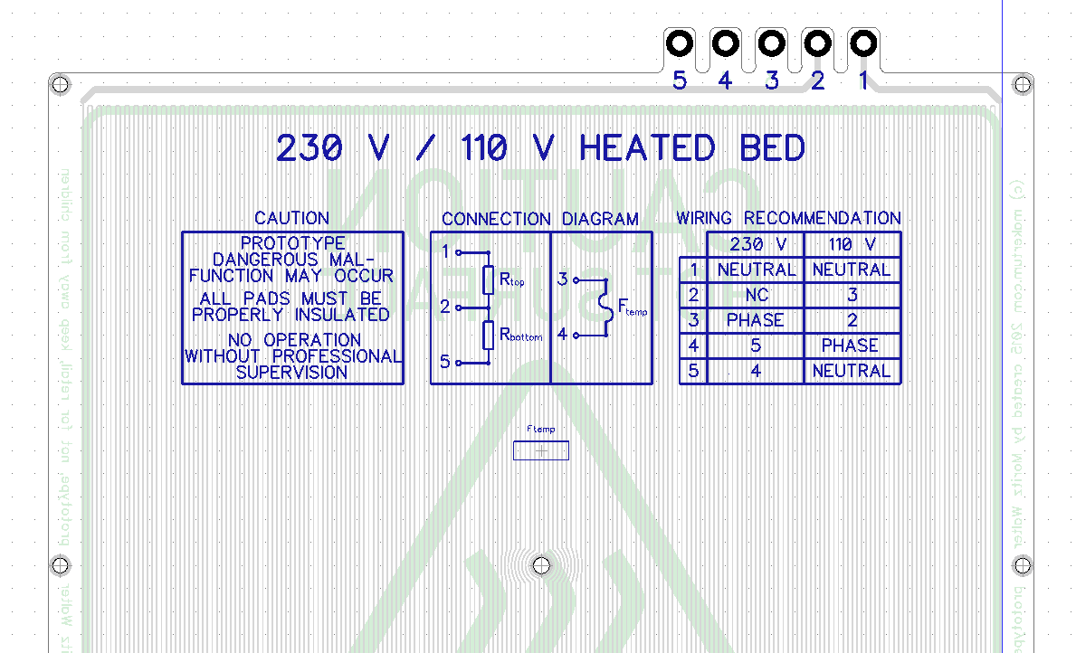
Silk screen documentation
The best documentation is the documentation you have at hand, so I included the connection diagrams and wiring hints on the back side.
Three point leveling
I know some of you prefer the option of using a simple three point leveling, so I moved the LED circuit a bit to the side and added a "third" mounting hole to the front, left and right side of the board.
Discussions
Become a Hackaday.io Member
Create an account to leave a comment. Already have an account? Log In.
two questions i have to ask you.what is width of the board ? And if the 80.000 mm are from both sides of the board or just one.thanks
Are you sure? yes | no