 Moritz Walter
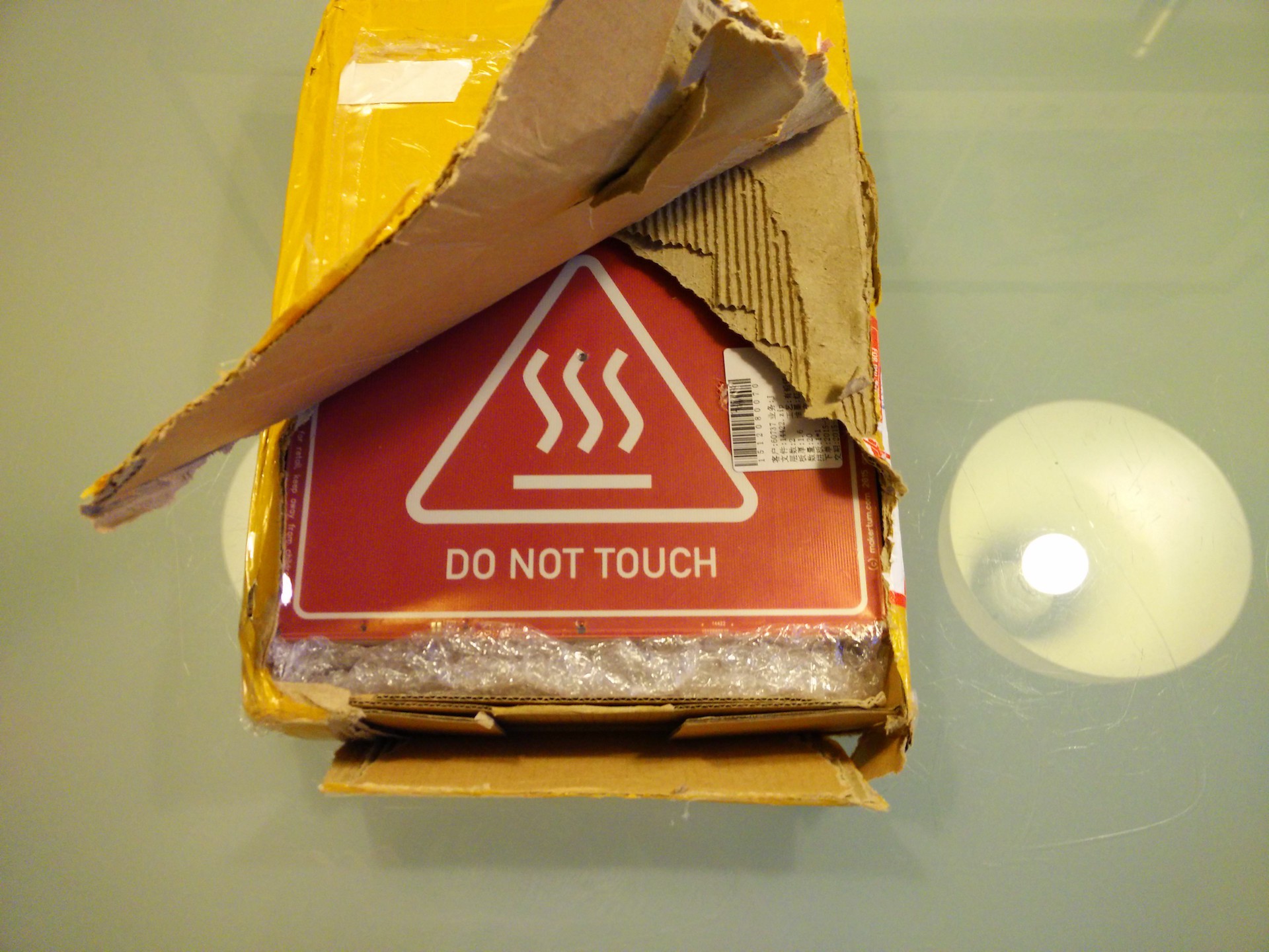
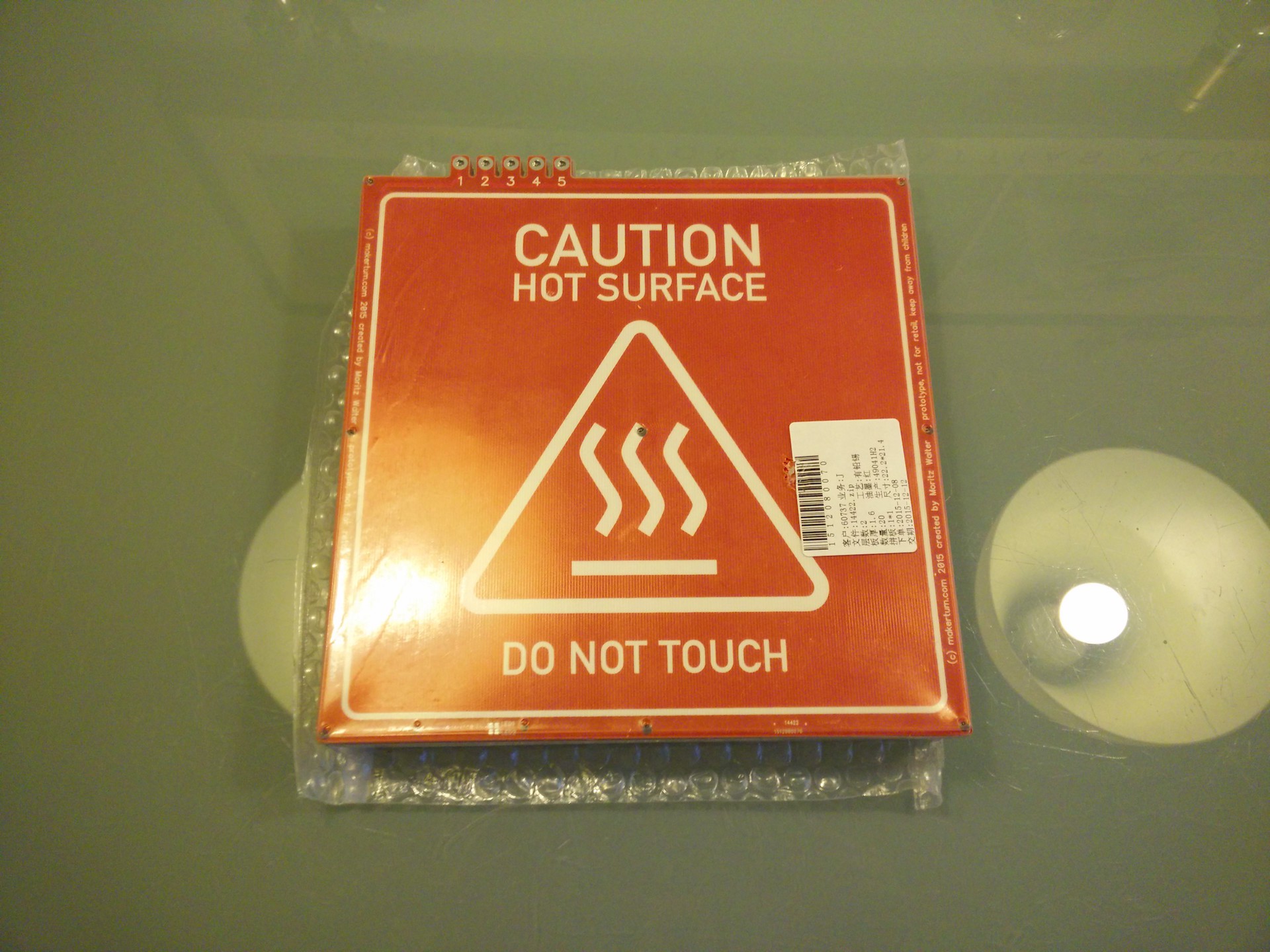
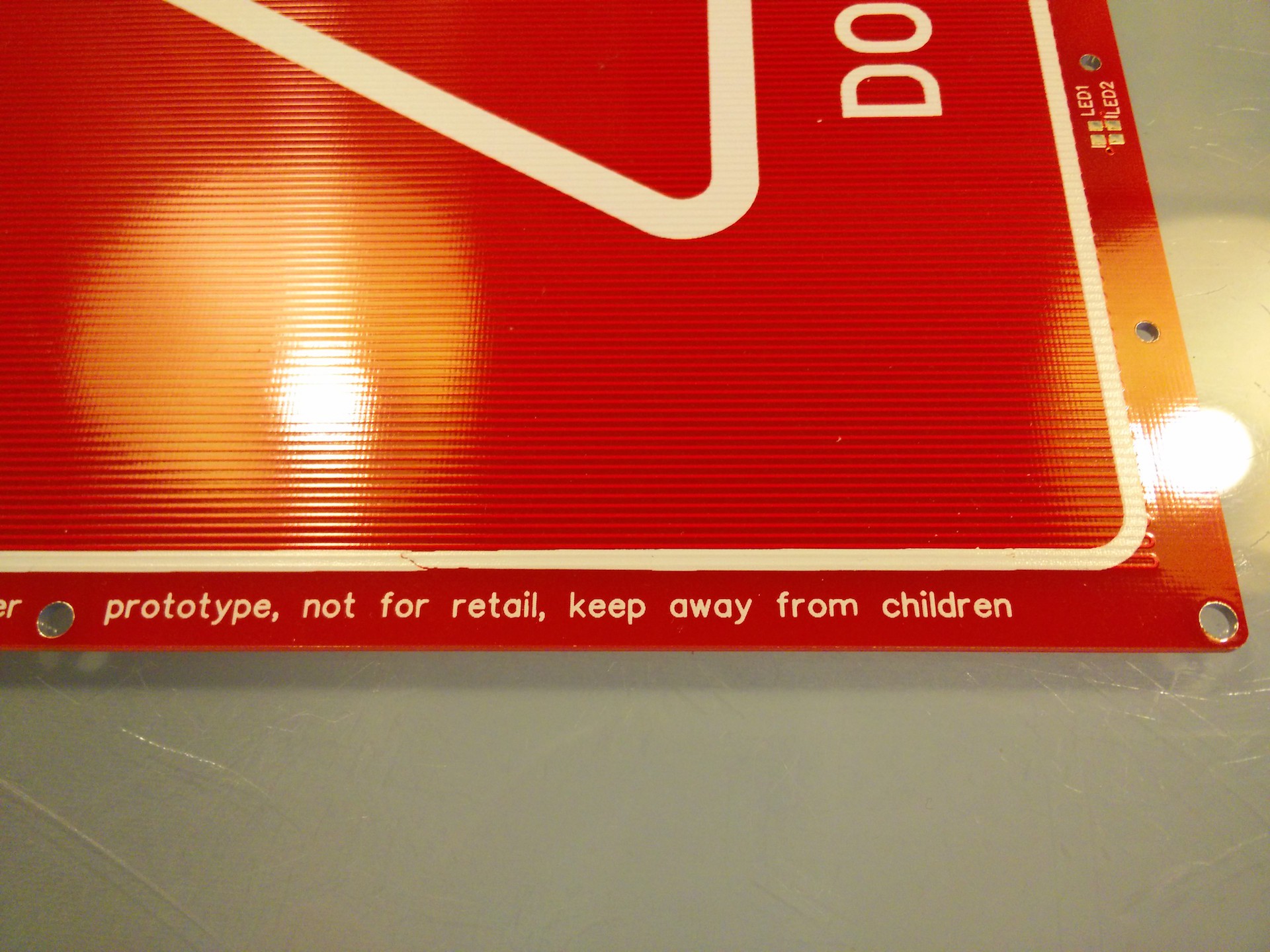
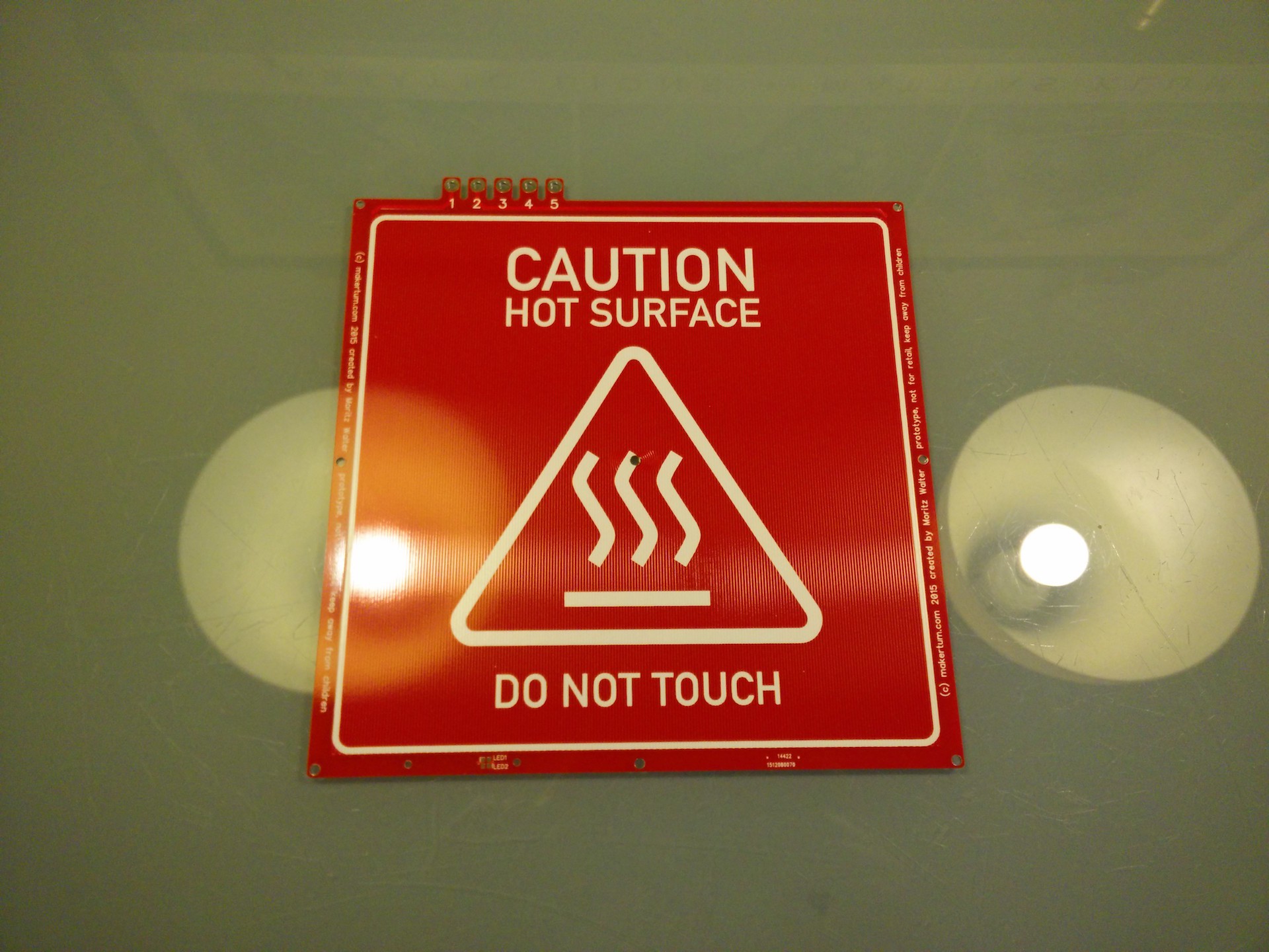
Good news everyone, the first batch of 20 heated beds arrived today. They do look fantastic and are expected to work as they should. So first, enjoy the pictures, and then I'll also look into the electrical properties of the boards and compare the actual to the design specs.
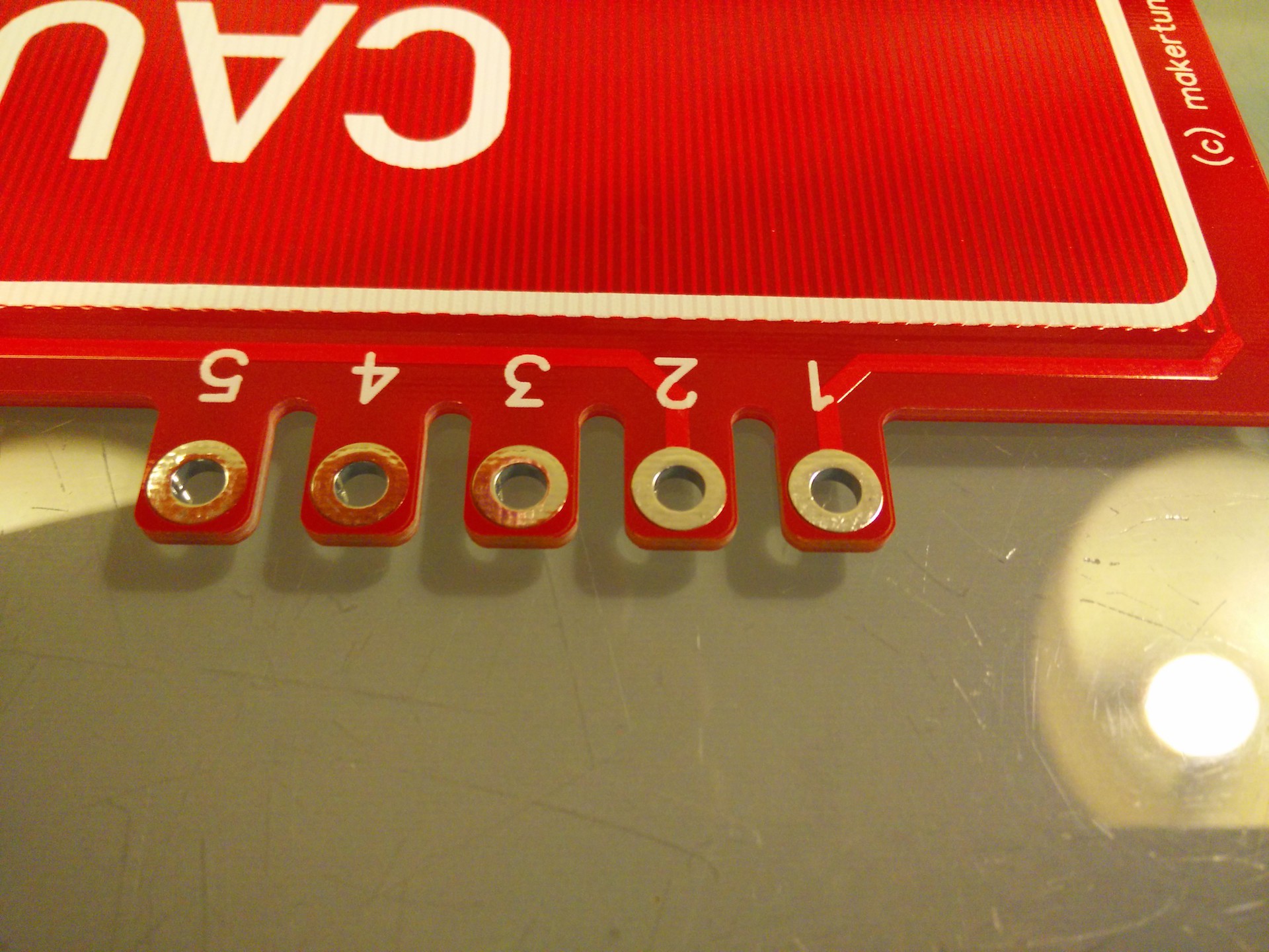
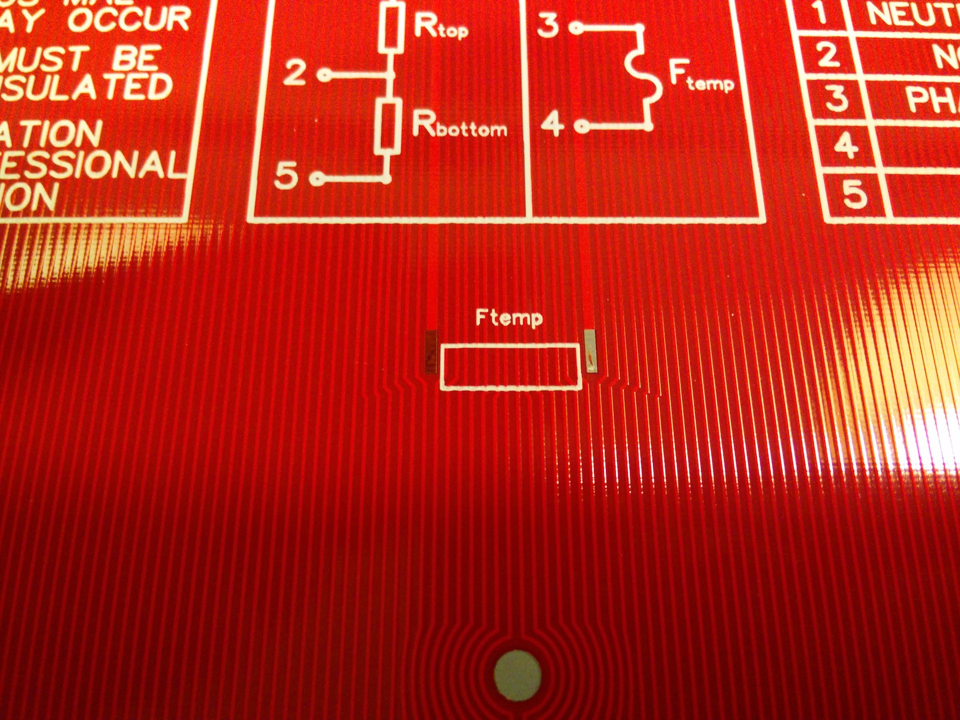
Pictures
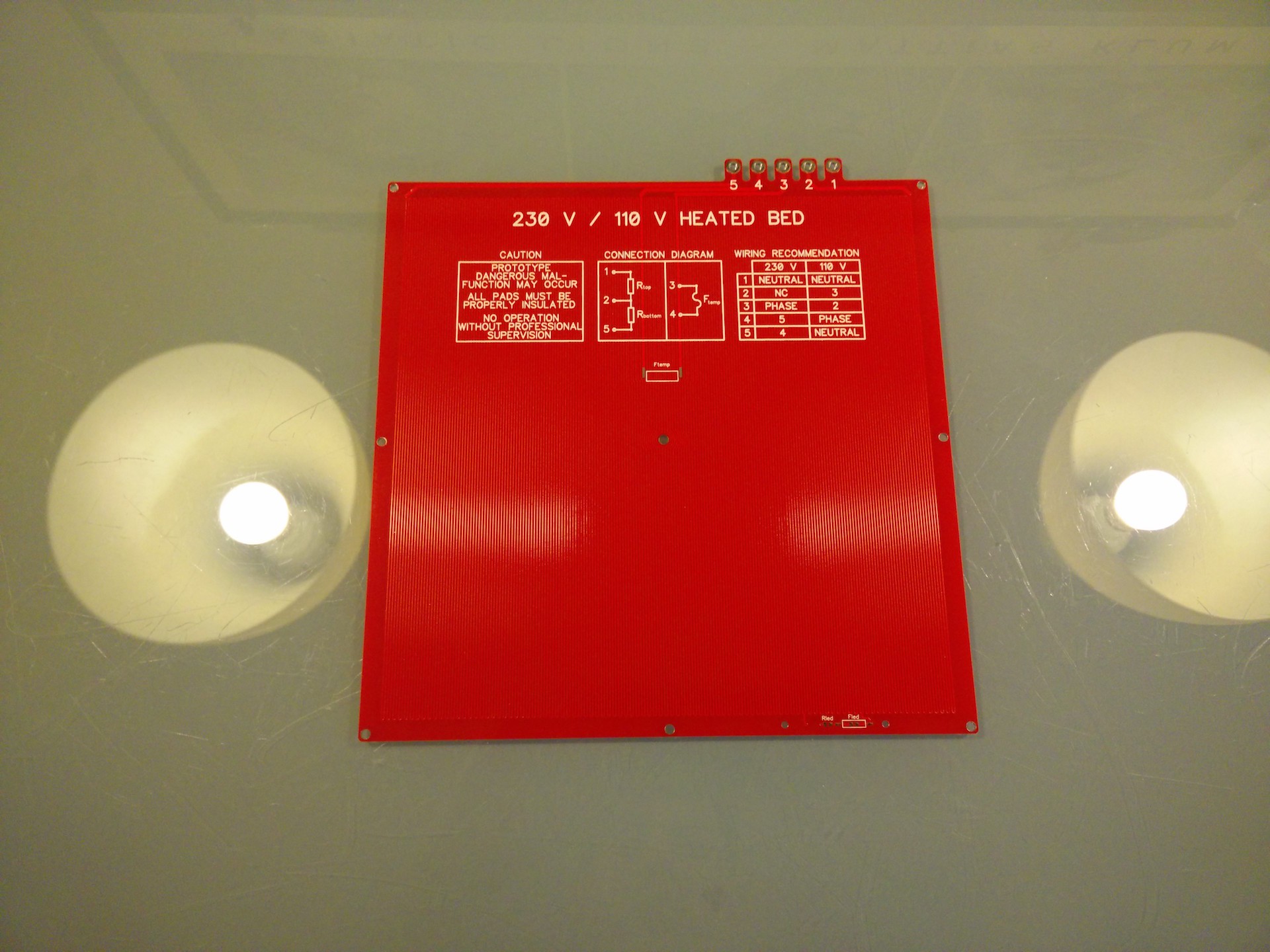
Actual properties
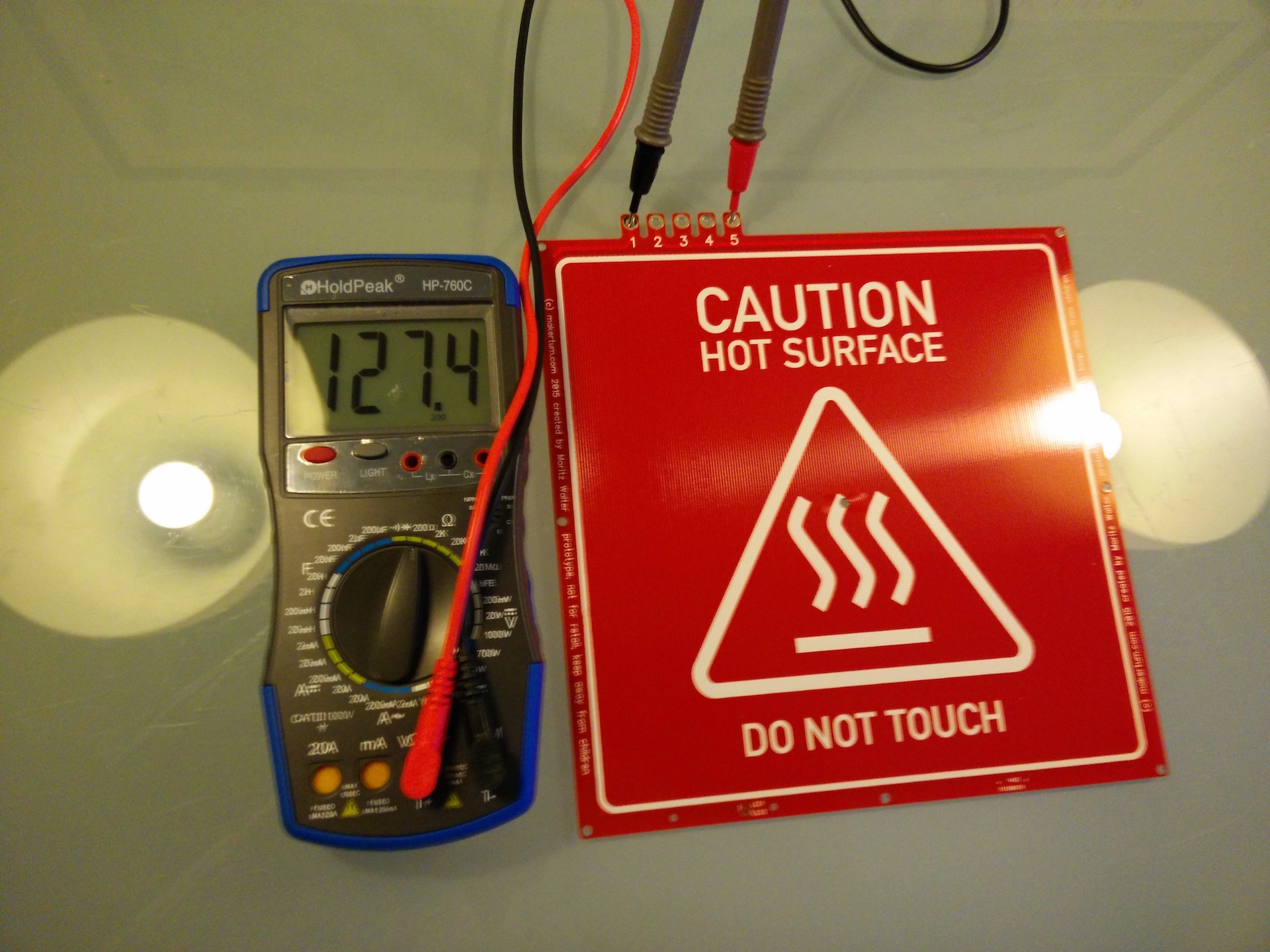
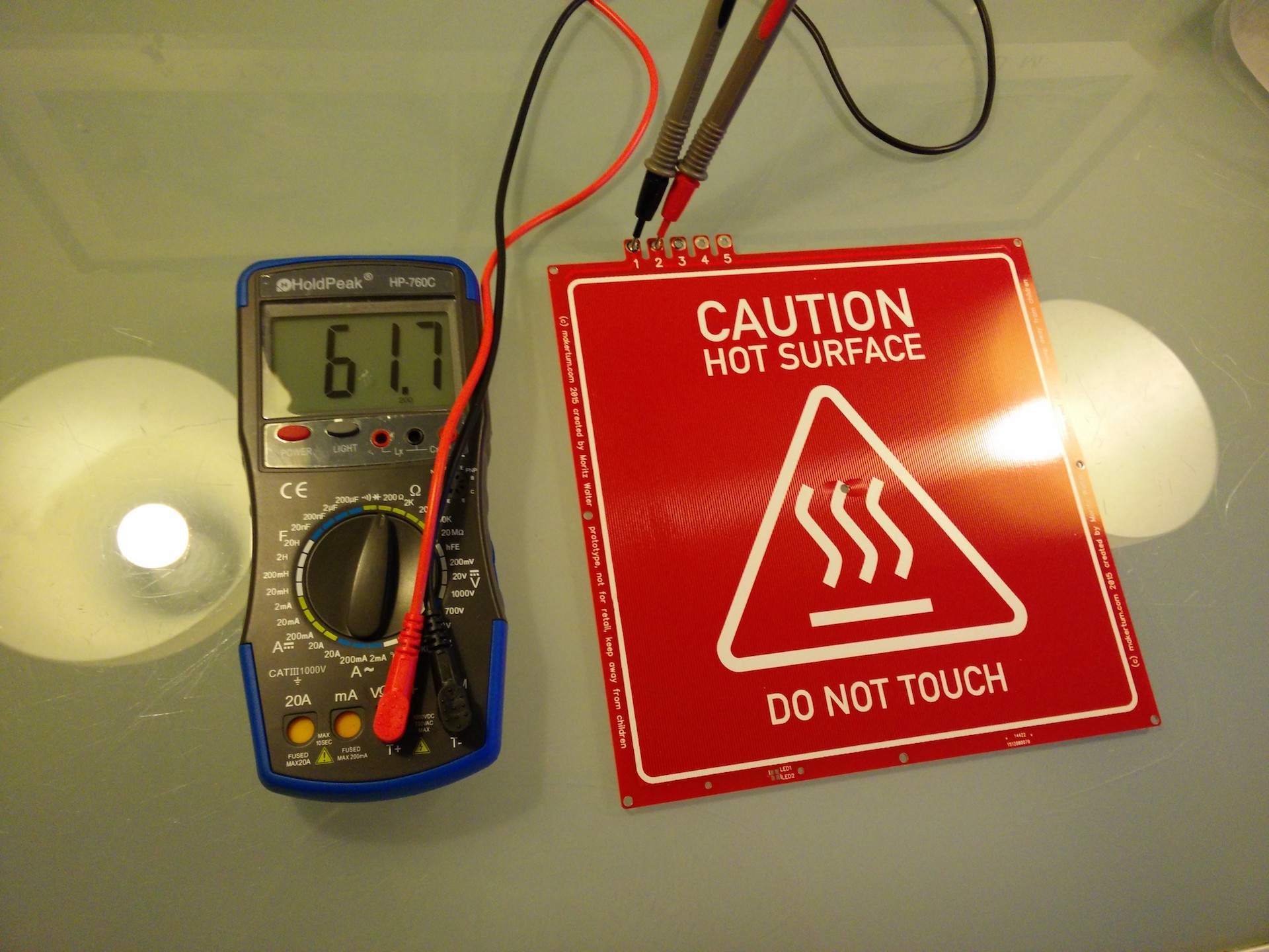
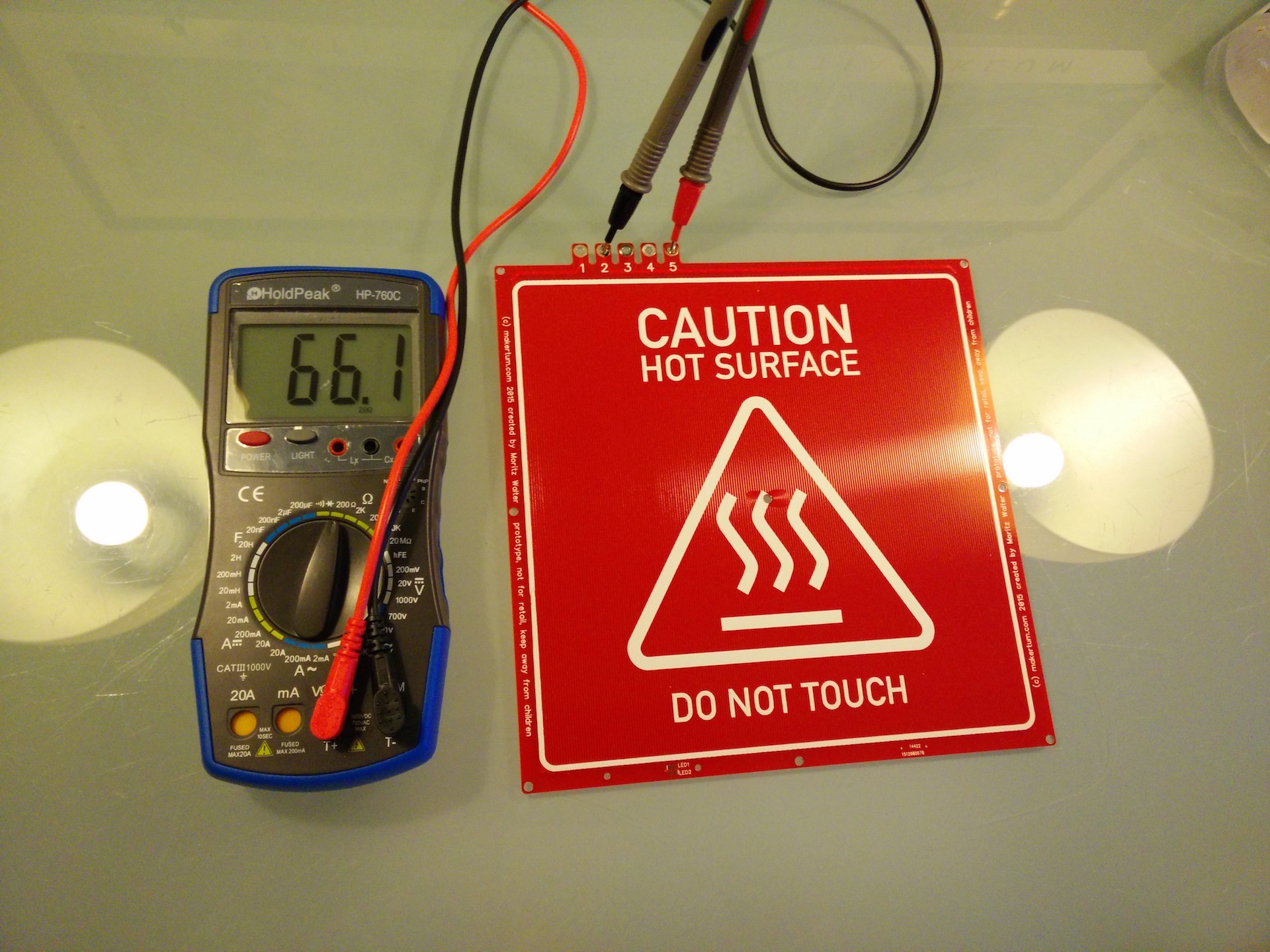
As you can see below, the full trace has about 127 Ω, which is about 20 Ω (or 20 %) more than my math suggested. That sounds (and is) much, but only means that they'll output 20% less power than expected, which is still 400 W.
The difference probably comes from a combination of several factors in the manufacturing of the PCBs. First, the copper thickness, for which I assumed the 34 µm a 1 oz copper clad suggests. Then the copper conductivity, which can also vary widely, especially if you have no idea about what value to start with (I assumed 0,017 Ω*mm/m), and eventually, the geometrical manufacturing accuracy, since the "precisely" 0,37mm wide and about 80m long heater trace is an extreme case that pushes the specifications a manufacturer can guarantee for to the limits.
Since our board has two sides, we can at least get a clue of what magnitude the actual tolerances are in, and where I just guessed wrong. Below you can see how the resistance of the top layer differs from the resistance of the bottom layer by about 7% and we can actually make a good guess what's causing this. Since the offset tolerances are insanely low, it's impossible that the geometrical differences between the top and the bottom layer are 7%. Assuming that top and bottom side use somewhat the same copper, it must be due to tolerances in the copper thickness. Mind that this is just one sample, so all it tells us is that the copper thickness can be off by 7%.
Next steps
So, even if the boards are a little out of spec, 400 W is still a value that will work perfectly for 3D printing and will significantly improve heatup times for most. That means, that I can start testing the boards and see if they survive the high temperatures. I will probably setup a safe testing environment where I can let the board run continuously for 30 days or more simulating heatup and cooldown cycles, regular printing temperatures of 110 °C as well as extreme scenarios like long term stress tests at 130 °C.
I'll also soon place some orders on further parts for the boards, like LEDs, fuses and polycarbonate sheets for milling the LED covers. So if the testing is successful and no bad things happen, this first batch will go out to betatesters as self assembly kits with all the necessary components. So if you're interested in trying this out, just send me a PM or post a comment.
Discussions
Become a Hackaday.io Member
Create an account to leave a comment. Already have an account? Log In.