 ajlitt
The RPF cut corners on the Pi Zero to get down to $5. One omission in particular leads to another opportunity for expansion. By leaving the HAT header unpopulated there is no longer the restriction of stacking HATs on only one side of the board.
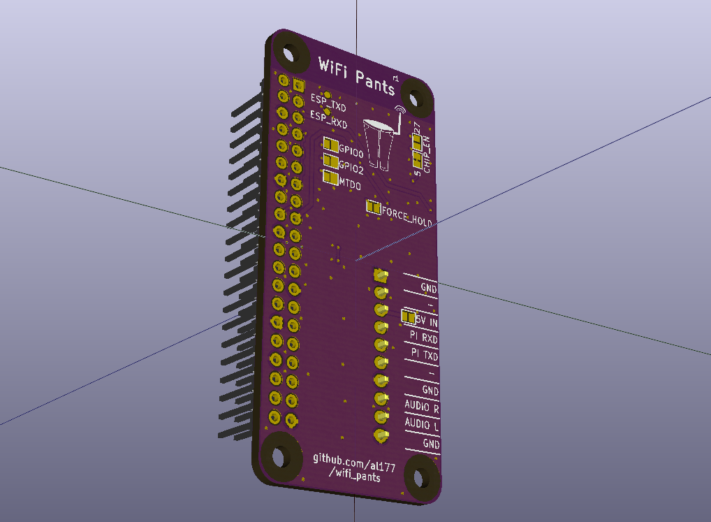
I present to you: PANTS
 A Pi Zero gets stacked and soldered on top. The header pins are extended so HATs can be stacked on top of the Pi.
There's also a logo. I am not proud of this.
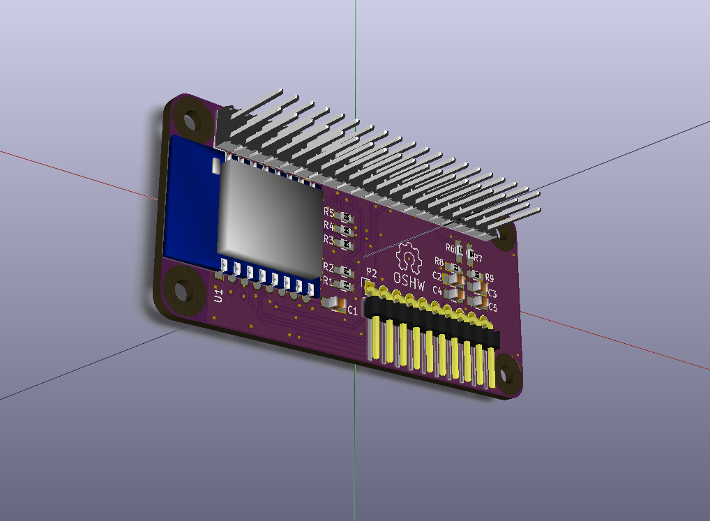
These pants use an ESP-12E/F module to avoid dealing with the FCC based on what I was working on in the last post. For a USAnian the ESP-12F isn't much more expensive than the ESP8266 chip plus the discretes to go around it, and much less after adding in NRE for certifications on a low volume specialty product. This does mean a downgrade to 1-bit SDIO, but in practice it should be speedy enough for the aging BCM2835.
In all the extra space I put down a 10-pin header for an FTDI 6-pin USB-to-serial cable (old Arduino style), +5V in, and audio out via the PWM GPIO hack. I went with the simple low pass + DC blocker filter used on the original Pi rather than the fancier buffered one on B+ and later to keep it cheap. If you want quality, get a USB DAC or use one of the existing I2S DAC HATs.
The 5V input is disabled by default, but when enabled by a solder jumper can power the Pi from the 5V USB on most FTDI 6 pin cables.
I also have cut-and-jumper pads to switch the CHIP_EN GPIO from GPIO5 to GPIO27. GPIO27 is an alt for the SD_D3 SDIO signal that's unused in 1-bit SDIO mode, and I think can be remapped with a devicetree overlay as a normal GPIO. This would free GPIO5 for other applications while using up a GPIO that would be taken up by SDIO anyway.
New Github repo to the left.
In other news, I did get the v0.2 of my HAT design back from OSHPark. The boards look good, but since I think the module design is more practical I'm in no rush to build one up.
Discussions
Become a Hackaday.io Member
Create an account to leave a comment. Already have an account? Log In.
@ajlitt You can dispense with the extra GPIO on CH_EN; reset the ESP8266 at every reboot by pulling the CH_EN low to turn the chip off, then it will take the two-stage firmware loading afresh.
The Videocore looks for the HAT EEPROM before putting up the rainbow splash screen - even with no HAT attached there's ~3.5ms of low-going pulses on both ID_SC & ID_SD at the Zero's J8 pin 27/28. I've pulse-stretched those to ~250ms, but it may work without doing that, simply take Pi ID_SD to ESP CH_EN.
Are you sure? yes | no
That's a good idea. Can the ID bus get touched under Linux? That would make it more difficult. Maybe a Schmitt trigger and RC tank, or an I2C port expander?
If it's always idle under Linux then it might be an option. But that means the driver can't be reloaded, only... more
Are you sure? yes | no
After the boot-time HAT eeprom probe, that I2C peripheral is used for the camera interface. As the Zero is without the camera port, I think it's safe under linux - that pin won't go low again unless it's by your choice (you can safely make use of GPIO0/1 or any alt function supported there). I'll have to check the behaviour on Pii with camera interface (ie whether after the HAT eeprom probe the camera continues to use i2c0 at GPIOs 0/1, or whether that peripheral is remapped to some other GPIO pins for the camera).
Are you sure? yes | no
Good news, it looks like the i2c0 peripheral is mapped to GPIO 0/1 for boot/videcore HAT eeprom probe, then remapped to 28/29 for camera usage. ID_SD & ID_SC GPIO 0/1 are are configured as inputs (pulled hi) under linux. I'll connect a camera later for confirmation.
Edit: OK, I've now tested with the camera attached on a model A+. All good. I get the boot HAT polling pulses on ID_SD, then when using the camera there is no further i/o on that pin. Furthermore, I can set the pin as an output & drive hi/lo as required. I'm not too familiar with i2c - will any HAT eeprom remain silent if we just waggle SD without clocking?
Are you sure? yes | no
@David Lowe Thanks for checking that out. I2C devices are supposed to tolerate SDA transitions while SCL is high. In the bus idle state SDA isn't valid until SCL transitions low, and even then peripherals don't do anything until they see their own address byte come across the bus.
I'm surprised there's no traffic when the camera is in use. I know most of those sensors use I2C as the control channel and the other serial bus only to stream pixel data.
Are you sure? yes | no
I was about to reply that this was a bad idea because we can't guarantee that the firmware won't suddenly decide to poke at the camera control bus.
Then I did some digging and found that the camera's I2C channel is going to I2C-0 through alts on GPIOs 28 and 29. That means that GPIO0 and GPIO1 are pinmux'd to I2C-0 only during HAT probe! Since the guidance is to never use the ID_S* pins for anything but HAT EEPROMs then this scheme should work.
I should have time to mock this up this weekend.
Are you sure? yes | no
I tested this out on one of my boards with the HAT EEPROM. I used GPIO0. The traffic during boot did not seem to properly reset the ESP8266. This could be due to the EEPROM on my board being unprogrammed (all 0xff), so the I2C commands may not be generating a long enough active low pulse for the ESP to reset.
However it works great if I manually set GPIO0 low and high again. I also checked that it doesn't mess with the VC's ability to read the HAT EEPROMs by writing a valid image with the EEPROM tools and verifying that the hat driver in devicetree populated the values I programmed after a power cycle.
Thanks for all the work! I'm adding this on my next board.
Are you sure? yes | no
@ajlitt if the 3.5ms minimum ic2 pulse train isn't sufficent to reset the esp, then pulse stretch it as I have. I use a diode cathode to ID_SD, anode to centre of a simple R-C timer circuit ~250ms. Thus ID_SD can discharge the capacitor when it goes low, and a high transition can't charge the capacitor so doesn't affect the RC time delay. A pair of FETs produce a nice square low-going pulse.
Or use a 555 timer, would be nice to see one of those classic chips on a Pi board :)
Are you sure? yes | no
That's an interesting way to do that. I was considering using a transistor to buffer the RC delay but that's even simpler.
However I'll just run ID_SD directly to the ESP CHIP_EN since I want the driver to positively control the enable during the firmware download process. That saves putting 4 discretes on the board.
Are you sure? yes | no
When running linux, the camera's i2c0 is GPIO28/29 alt 0. It's no longer configured at GPIOs 0/1, they're set as inputs. I've further confirmed this with a mulimeter - there's no connection between the camera connector's i2c lines and ID_SD / ID_SC on the 40 pin header. Those pins are marked DNC, I think everyone else respects that, so we are safe to use ID_SD as an output should you want to reset the ESP8266 manually under linux (and we get the reboot reset for free).
Edit: sorry I didn't see your second reply before posting the above. It does work, I've tried it ;-) But I haven't had the need to do a manual reset, it just runs and runs, even after sudo reboot.
Are you sure? yes | no
Another small thing you could add in the next version: mark the pins that the pants are using somehow (circles around them on the PCB maybe), so that it's easier to avoid conflicts. This is a really great project, I can't wait to use it.
Are you sure? yes | no
Good idea. I was thinking of recommending that the in-use signals be snipped short on the long portion of the header so it doesn't pass through to any HATs. But I can modify the footprint to make that easier to follow.
If I were to sell these, I'd leave the header unsoldered. That way the user can choose which side of the Pi to mount it on, long or short pins depending on if they want to feed through to a HAT, and the option to use a socket instead of pins so it can be used like a HAT on the other Pis.
Are you sure? yes | no
Is there a reference page anywhere which tabulates GPIO usage of all the HATs & plain expansion boards out there? Thus we could see which are SDIO 4bit mode (!22-27) & 1bit Pants mode (!22-25) compaitible?
Are you sure? yes | no
I started with this to find pins with only GPIOs as usable alt functions: http://elinux.org/RPi_BCM2835_GPIOs . The GPCLK pins like GPIO5 stand out, so that's what I picked.
But you got me thinking about creating such a list. It's probably impossible to document and steer clear of GPIOs on every HAT out there. Still, we can try to at least look at supported devices. Using sed I was able to get these GPIOs from the device tree overlays in the 4.1 kernel source:
15
17
18
22
23
24
25
26
27
4
5
So it looks like my GPIO 5 is being used already by a couple of drivers. The SDIO bus at 22-27 are used by a couple of HATs. 22-25 is inevitable in 1 bit mode, and 27 is used only as a button on the tinylcd35 (as is 5). Suspiciously absent is GPCLK alt GPIO6 on pin 31. Maybe this is because this was an enable used for the USB/NIC chip on the pre-B+ Pis? Anyway, I'll move my cut-and-jumper to GPIO6 instead on the next spin if GPIO27 doesn't work out.
Are you sure? yes | no
Striking out the pins of the useful & immovable peripherals (i2c0/1, spi0, serial, i2s, sdio) you're left with a set of io at 4/5/6/16/17 for general purpose (add in 12/13 if you don't want PWM audio).
Unfortunately, as the sdhost hardware block has only recently been utilized for SDCard duties, thus freeing up the mmc peripheral for sdio, 22-27 seem to have been included in that set of GPIO too. The Sense HAT seems a typical example - uses SPI & i2c, but chooses 23-25 for its attiny.
The message needs to go out "get off my lawn" re 22-27 & future HAT designs!
Are you sure? yes | no
The pi zero and in particular the metal SD card slot covers the WiFi antenna? That's probably not too good. Have you looked at all into the flash powerdown command I posted about before? Is this board still wired up for 4 bit sdio for, alternately, those who choose to remove the flash? Thanks for all your efforts.
Are you sure? yes | no
Agreed on the antenna, and something I'll fix in the next spin. I tried placing it so the antenna hangs offboard, but the solder pads for pins 1, 2, 21, and 22 of the module would run into the keepouts of the mounting holes. I really wanted to get TXD and RXD to test points for debug, which are pins 1 and 2. But now that I think about it, I'm a bozo for not considering soldering to the nice plated tops of the pads on the module if I want access to those. I sent the files off to fab yesterday, so at this point I'm hesitant to spend another $15 without waiting for the current design to come back for bringup and bugfixes.
So in the next rev I'll take those 4 pads off the footprint and move it over. Thanks for the sanity check.
I set out to add 4 bit SDIO, but gave up because it made length matching of the 6 signals difficult. The SD_D2 signal on pin 37 is significantly far from the rest of the SDIO signal cluster and required too many vias and ground plane splits on this 2 layer board than I wanted. I solved this on the previous boards with some careful meandering of the bus, and was kind of lazy on this one. I think that moving the antenna offboard might give me enough room to do it on this. I also haven't considered moving the module (and likely all other SMT parts) to the back side, so the flipped bus ordering may make it easier.
I haven't investigated the flash sleep option though. On one hand, you are likely right that nobody would ever see SDIO randomly hit on a valid wakeup pattern. On the other, I'm paranoid. My day job involves thousands of instances of whatever I'm working on in a single installation, so I'm all too familiar with "once in a billion hours" faults occurring once a day in a system. I'm willing to hack up my ESP-03 prototype to test that theory, but I don't think any of us could test this sufficiently to say that it's significantly unlikely to cause problems.
Are you sure? yes | no
Is length matching preferable or a necessity? My hairball SD card slot gives ~18MiB/s reads from cards, and the ESP-03 mounted on a microSD adapter gives ~ 8Mib/s (low given a 54Mib WiFi connection). Do we even know if the those lines are length matched between 2835 balls & pin headers?
Are you sure? yes | no
@David Lowe I don't know. I still haven't run into anything I'd characterize as an SI problem with any of my boards. My v0.1 board had something like 6mm of skew and it works fine. We also don't know how much skew the module adds between the ESP8266 and the castellations.
But I figure that it's best to match them closely so as not to add to the skew on the other two boards.
Are you sure? yes | no
Length matching is unnecessary. Length matching is a timing issue.
SDIO is 50MHz, you have 20ns period. Even 8 inches of tracks skew would only eat up 1ns of budget which is 5%. Now when you get up to 200MHz, then you might want to think about it.
SI issue is a bit different, you would be looking at actual signal quality. i.e. things like terminations, where decoupling caps should be and how long their breakouts, return paths and to avoid splitting ground reference plane with traces,. etc.
Are you sure? yes | no
Thanks for the info. I haven't looked into sdio signaling and hardware enough to say whether it could definitely be done, but seems that since the wakeup pattern involves multiple pins and specific timings it could be possible to engineer the driver to avoid said pattern. Maybe sprite_tm can advise on this?
Are you sure? yes | no