 Yann Guidon / YGDES
The decimal display is a nice additional feature but it puts some more pressure on the design. The pressure was reduced when I found that the 74HC74 could drive the MOSFET directly (instead of using the Flash to decode one bit to 2 outputs) but the requirement remains: the display needs a fifth digit that can range from 1 to 6.
With 3 bits, it's not too hard to decode 3 bits to the required 6 segments, using a few diodes.
| digit | A | B | C | D | E | F | G |
| 1 | * | * | X | ||||
| 2 | * | * | * | * | X | * | |
| 3 | * | * | * | * | X | * |
- Segment F is not implemented.
- Segments A, D and G are on for 2 OR 3
- Segment E is on for 2 (directly)
- Segment C is on for 1 OR 3
- Segment B is on for 1 OR 2 OR 3
Total : 7 diodes only. However this limits the display range to 39999(d). Adding the 3 other digits (4, 5 and 6) is a bit more tricky but the principle is roughly the same, adding the F segment but trying to squeeze as many codes inside 4 bits. 3 bits are enough to code values from 0 to 7 but hopefully we can predecode some things and avoid using an external 74HC138...
| digit | A | B | C | D | E | F | G |
| 1 | * | * | |||||
| 2 | * | * | * | * | * | ||
| 3 | * | * | * | * | * | ||
| 4 | * | * | * | * | |||
| 5 | * | * | * | * | * | ||
| 6 | * | * | * | * | * | * |
At this point, the codes 1 to 6 should be recoded to an intermediate 4-bits code which requires only OR logic (implemented with diodes).
The segments A-D-G are often ON at the same time so it's a first line of optimisation. Negative logic is another angle of attack (it worked well with the diode matrix). 5 and 6 differ only by the F segment so there is more hope to find an intermediary recoding.
One code (Z) is assigned to segments A-D-G, which covers codes 2-3-5-6.
Code Y controls segments B and C for the codes 1-3-4.
Sor far we have:
- 1 = Y
- 3 = Z + Y
4 codes remain with only 2 bits left. Bit X is assigned to segments C-F-G to form one part of the numbers 4-5-6. X overlaps with Y (segment C) and Z (G) but they are ORed with the diodes so there is no problem.
- 4 = X + Y
- 5 = X + Z
Digits 2 and 6 remain and get code W, which directly controls the E segment.
- 6 = W + X + Z
This pre-decoding requires a few diodes to transform the 4-bits WXYZ code (output by the Flash chip's 4 data lines) into a 7-segments digit. However a tiny extra logic is required to implement the digit 2. This is not convenient because it can't be solved with a diode, as a OR function. A AND function is required, hopefully implemented with a single transistor.
2 and 6 differ by the X code:
- 2 = W + Z (X=0)
- 6 = W + X + Z (X=1)
So the B segment's equation would be
B = Y or ( W and /X )
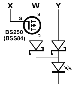
W is active ONLY for 6 and 2 so the electronics can be simplified, using a P-MOSFET (and a diode). I'll have to check this though...
The resulting equations are:
0 =
1 =         Y
2 = W +         Z
3 =         Y + Z
4 =     X + Y
5 =     X +     Z
6 = W + X +     Z
Converted in Hexadecimal with W=1, X=2, Y=4, Z=8,
0 = 0
1 = 4
2 = 9
3 = C
4 = 6
5 = A
6 = B
(All the codes are different so we're good).
The 4 pre-codes are :

Outside the Flash, we have :
A = Z
B = Y or (W and /X)
C = X or Y
D = Z
E = W
F = X
G = X or Z
4 segments are directly driven by the Flash output. The others are 3× OR2. That's 6 diodes and one P-FET only :-)
Update 20151214
While laying out the PCB I realise that some diodes could be saved thanks to the multiplexing... Is it possible to use only 2 output pins ? This would simplify the rest of the PCB layout and segment assignment.
| ph.1 | ph.2 | |
| A = D = Z | * | |
| B = Y or (W and /X) | * | * |
| C = X or Y | * | * |
| E = W | * | |
| F = X | * | |
| G = X or Z | * | * |
Some things are pretty easy :
- E and F's cathodes are connected to the phase 1 low-side transistor.
- A and D's cathodes are connected to the phase 2 low-side transistor.
The others are on during both phases so they are tied to 0V. It gets more complex but we can split the signals in two phases :
- Phase 1 : W and X
- Phase 2 : Y and Z
For G or C, it's possible that X coincides with Y or Z so there is no decoding at all, but the other needs more decoding, in the form of a MUX2 driven by the phase signal. Hey, I just got some cheap 74LVC1G157 that do that.
Segment B is a bit more tricky though. Basicly it's tied to Y/W but turned off if X is 1 during a certain phase.
So far we know that the Flash pins are tied to the segments this way :
- pin F1 : W (phase 1) / Y (phase 2)
- corollary : pin F2 : X (phase 1) / Z (phase 2)
Thus:
- A = F2 - ph2
- B = F1 (and some logic with F2 and ph1/2) - /CE
- C = mux2(ph1/2, F1, F2) - /CE
- D = F2 - ph2
- E = F1 - ph1
- F = F2 - ph1
- G = F2 - /CE
It's pretty simplified now ! No more diode ! There's a catch though. The light output of B/C/G can't be directly modulated. One simple solution is to tie their cathode to the /CE pin.
B must also be decoded. If needed it's possible to get the negative /CE signal, from the 2-gates oscillator. Phase can be chosen (1/2) as desired to simplify the circuit.
B = F1 and (/F2 and/or somephase) (and don't forget /CE)
This turns into a complex equation but the AND can be broken down easily because the LED must be powered from both ends. For example, B is ON when (F1 and /CE)=1 on the anode, and (/F2 and/or somephase) = 0 on the cathode.
The high side (anode) can be driven by the previous BSS84 trick (P-MOSFET) or a ANDN gate. The MOSFET is probably not electrically efficient (I'm not sure I have the right reference in stock) and it's tricky to get a cheap single-gate ANDN. But C uses a MUX2 and these gates can do a lot more than selecting one input (and I have stock :-) )
The low side can be reduced to a OR gate that can be implemented with a couple of diodes (on F2 and one phase1). The Shottky's drop requires a specific series resistor value. However the MUX2 can also implement a OR gate. In other words...
More accurately:
- high side=1 when /CE=0 and (W/Y)F1=1 {else 0}
- low side=1 (to clear the segment for the code 6) when (W)F1=1 and (X)F2=1 and ph1=1
Ooops that's AND3...
Wait
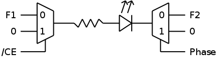
The MUX2 on the left is useless because F1 is floating when /CE is high. So it's more like :
(phew, I feared I would have to add another MUX2 gate)
Update 20160704: I've manually checked all the equations from the latest version of the schematics, just in case, and it works.
Value:
0
1         Y
2  W         + Z
3          Y + Z
4      X + Y
5      X +     Z
6  W + X +     Z

Intermediate coding:
W = F1, ph=1 (phase 2)
X = F2, ph=1 (phase 2)
Y = F1, ph=0 (phase 1)
Z = F2, ph=0 (phase 1)

Segment decoders (high side && /low side)
A = F2 &&  ph=0
B = F1 &&  F1 & F2 & ph=1
C = (F1&ph=0)|(F2&ph=1)  && /CE
D = F2 && ph=0
E = F1 && ph=1
F = F2 && ph=1
G = F2 && /CE
In 3 cases, one segment is turned on during both phases:
- segment C for value 4
- segment G for values 5 and 6
But this is not critical and I can proceed to route the rest of the PCB.
Discussions
Become a Hackaday.io Member
Create an account to leave a comment. Already have an account? Log In.
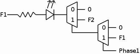
Just added a little illustration to better explain my system ;-)
Are you sure? yes | no