 Ted Yapo
I couldn't sleep last night. At least I came up with an idea (it might be lousy). I wondered how far forward you could push the mixer (correlator) in this system. Maybe it could be moved all the way up to the photodiode, analogous to direct-conversion RF receivers?

In this circuit, two SPDT CMOS switches flip the diode from one polarity across RC to the other, synchronous with the transmitted signal. Any DC light component will cancel out since the photodiode will alternately charge the capacitor one way, then the other. In contrast, modulated IR received from the transmitter will be in phase with the switching, and add constructively to charge the capacitor to a DC voltage. This DC voltage can more easily be amplified using precision op-amps, or even chopper amps, since the detected voltage may be very small in some cases. The operation is similar to direct-conversion RF receivers, where the gain takes place at baseband after down-conversion.
There could be any number of issues with this circuit, including limitations of the CMOS switches. Two possible problems come to mind: charge injection and switch leakage currents. Charge injection is when operation of the switch causes a small of amount of charge to be injected (through the MOSFET gates) into the switch contacts. I will have to look into how well-matched typical switches (on the same device) are in their charge-injection characteristics. If the switches are very well matched, the symmetry of the balanced circuit above should mitigate the effect. There is also typically a trade-off between switch on-resistance and charge injection, so I may be able to optimize the design by choosing the correct switch. This Maxim application note discusses these issues and how to select a switch.
The second problem with CMOS switches is leakage current. In this case, current leaks through the internal parasitic diodes of the MOSFETs comprising the switch and into the switch nodes. Again, I can select low-leakage switches and try to find ones with matched leakage currents that will cancel in the balanced circuit.
After a little thought, I've come up with this alternative, which requires a few more driving lines from the MCU, but should be more versatile:
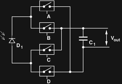
In this case, the SPDT switches have been replaced with four SPSTs, controlled with four digital lines {A,B,C,D}. The capacitor in this case is used to integrate the photo current from the diode. Four modes are possible. By closing either {A, B} or {C, D}, the capacitor can be discharged, resetting the integrator. You do this periodically or at the beginning of a measurement. With all switches open, the capacitor is disconnected from the diode. This mode is useful for holding the output constant for readout: it's a built-in sample and hold. Finally with either pairs {A, C} or {B, D} high, the circuit performs as a mixer in one or the other phase (correlating with a transmitted zero or one).
Although I probably have to use something a little more exotic for good performance, I have a tube of 74HC4066s around here somewhere that I could breadboard up pretty quick to see if this works at all. I can use a large-area diode and hit it with a lot of light, too :-)
References
http://www.analog.com/media/en/training-seminars/tutorials/MT-088.pdf
http://www.ti.com/lit/sg/slyb125d/slyb125d.pdf
https://www.maximintegrated.com/en/app-notes/index.mvp/id/5299
Discussions
Become a Hackaday.io Member
Create an account to leave a comment. Already have an account? Log In.