Vince
VinceThe Technogym manual indicates that the RF HR receiver outputs a 5V and 30 ms pulse for each heart beat.
A ESP32 with abilities will be the perfect µc. It's a easy job for it to read the incoming HR value and to output a pulse. Since the ESP32 works with 3,3V, we will need a 3,3V to 5v converter (see added file).
Thank's to Andreas Spiess with his Swiss accent, for his videos....
1. BLE Heat Rate sensor
Above the old T31 RF HR sensor and the smart one ....

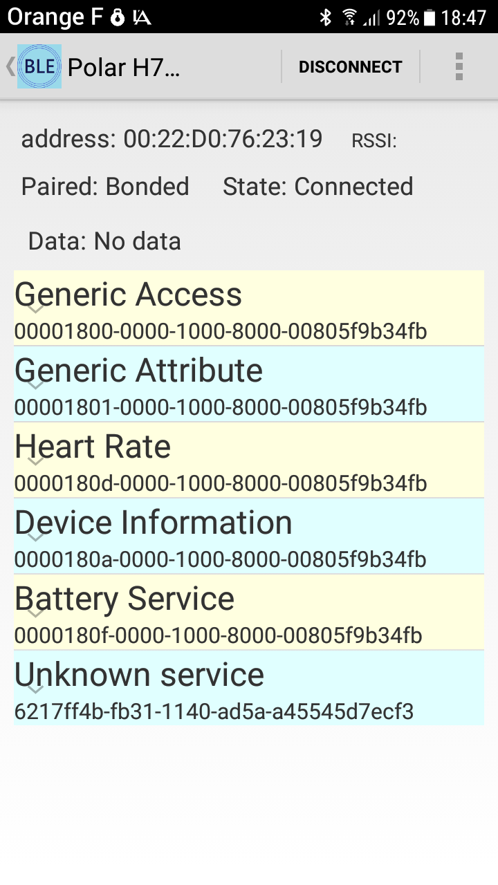
Here you can find the detail of the data shared by the BLE sensor.
You can clearly find the Heart Rate (UUID 0x0180a) and the battery service (UUID 0x0180f).
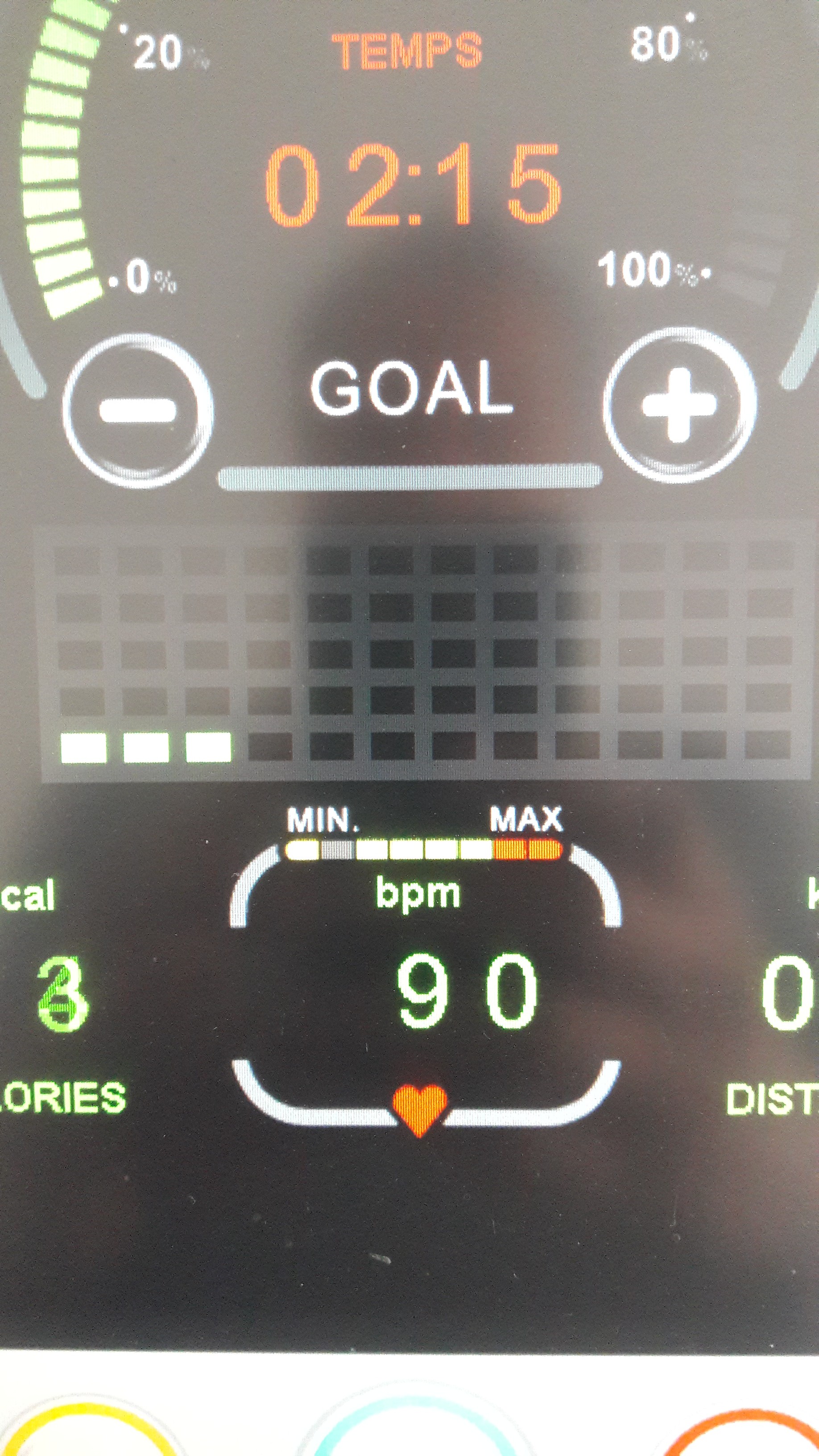
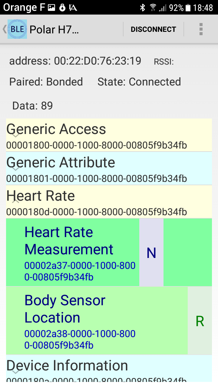
The Heart Rate service contains 2 informations : The Heart Rate value itself (N for notification) and the Body sensor location (Read) that we will use to verify if the value is valid or not). By the way, my HR was 89 bpm...
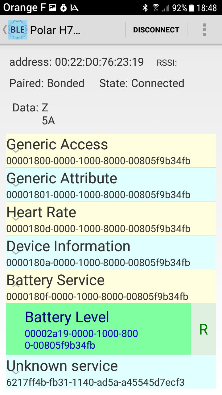
The Battery Level (read) is currently 5A (90%).
2. Connecting a BLE Device
The BLE Heart Rate strap sends a advertising witch is used by the ESP32 to listen server to connected to on start up.
The ESP32 scans for BLE devices but connects only the devices witch able to send HR and battery level data.
If a device with this services have been found, scanning and listening is stopped
// We have found a device, let us now see if it contains the service we are looking for.
    if (advertisedDevice.haveServiceUUID() && advertisedDevice.getServiceUUID().equals(service_HR_UUID)) {
        Serial.println("Found Heart Rate device! ");
        advertisedDevice.getScan()->stop();
        pServerAddress = new BLEAddress(advertisedDevice.getAddress());
        doConnect = true;
    }
.... and connection procedure is started
I used the ESP32 BLE arduino library by Neil Kolban.
3. We will have a quick look on the BLE services connection
The HR service needed is the UUID : 0x180D
and the characteristic you need is the UUID : 0x2A37
static BLEUUID service_HR_UUID(BLEUUID((uint16_t)0x180D));
static BLEUUID char_HR_UUID(BLEUUID((uint16_t)0x2A37));
Since this characteristic is send by the transmitter by notification, you have to register to get this notifications.
The second service is the battery level with the UUID : 0x180F
and the UUID of the characteristic is : 0x2A19
static BLEUUID service_BATT_UUID(BLEUUID((uint16_t)0x180F));
static BLEUUID char_BATT_UUID(BLEUUID((uint16_t)0x2A19));
This characteristic cannot be send as notification by the transmitter so I have read it directly (each 60 sec in my case).
Now I can connect the ESP32 on all this services and characteristics
// Obtain a reference to the HR service of the remote BLE server.
    BLERemoteService* pRemote_HR_Service = pClient->getService(service_HR_UUID);

// Obtain a reference to the BATT service of the remote BLE server.
    BLERemoteService* pRemote_BATT_Service = pClient->getService(service_BATT_UUID);

// Obtain a reference to the HR characteristic in the service of the remote BLE server.
    pRemote_HR_Characteristic = pRemote_HR_Service->getCharacteristic(char_HR_UUID);

// Obtain a reference to the BATT characteristic in the service of the remote BLE server.
    pRemote_BATT_Characteristic = pRemote_BATT_Service->getCharacteristic(char_BATT_UUID);

// Set notification
    pRemote_HR_Characteristic->registerForNotify(notifyCallback);
    pRemote_HR_Characteristic->getDescriptor(BLEUUID((uint16_t)0x2902))->writeValue((uint8_t*)notificationOn, 2, true);
3. Now I explain the way I output the pulse
Before using the data I check the sensor contact status. If ok HR value can be read. If not put HR value to zero.
if (pData[0] == 22 || pData[0] == 6) {
    if (pData[1] > 10 && pData[1] < 254) {                    // HR must be between 10 and 254 bpm
        HR_val = pData[1];
    } else HR_val =0;
} else HR_val = 0;
With the HR rate I calculate the delay between 2 pulses.
ms_pb = (int)60000/HR_val;
To output the pulse at the right moment I use an internal timer (not a delay() !!) witch is triggered by the calculate delay. I decided not to use the delay() function and rather a internal timer to have a accurate pulse.
The internal timer is first armed (at connection) by a 1000000 µsec delay witch is upgraded each time the previous pulse has been send.
Even the 30 ms pulse delay has been managed by a time survey (but not a internal timer this time)
Here the arming code :
// create a 30 ms pulse on pulse_pin
    pulse_on = true;
    pulse_off_at = millis()+30;

// rearm the timer with previous incomming ms per beat (ms_pb) value
    timerAlarmDisable(timer);
    timerAlarmWrite(timer, 1000*ms_pb, true);
    timerAlarmEnable(timer);
and the firing code :
// Create Pulse
    if (pulse_on) {
    if (millis() < pulse_off_at) {
        digitalWrite(PULSE_PIN, HIGH);   // turn the LED on (HIGH is the voltage level)
    }
    else {
        digitalWrite(PULSE_PIN, LOW);    // turn the LED off by making the voltage LOW
        pulse_on = false;
    }
    }
4. Battery indicator
The battery indicator is quite easy.
Each 60 sec. the battery level is red and displayed.
std::string value = pRemote_BATT_Characteristic->readValue();
String batt_caracteristic = value.c_str();
First I thought to display the battery level on a extra display but it's to much work for so a little information.
So I rather go for a led indicator that blinks for each decade (30% charge => 3 blink etc... ). That is so easier !
Again I don't want to use the delay() function but a timer. The code looks tricky ... it is !
batt_indicator -> It's time to give the battery charge level
batt_flash     -> Nb of flash needed (8 for 80%)
i_flash        -> Nb flash counter
init_time      -> for each flash set on/off time
// Battery indicator
if (batt_indicator){

    if (i_flash <= batt_flash){

        if (init_time){
            off_at = millis() + 40;
            on_at = off_at + 500;
            init_time = false;
        }

        if (millis() <= off_at){
            digitalWrite(led_pin, HIGH);
        }

        if ((millis() > off_at) && (millis() <= on_at)){
            digitalWrite(led_pin, LOW);
        } else if (millis() > on_at){
            init_time = true;
            i_flash++;
        }
    } else {
        i_flash = 1;
        batt_indicator = false;
    }
}
5. Let's go to the hardware
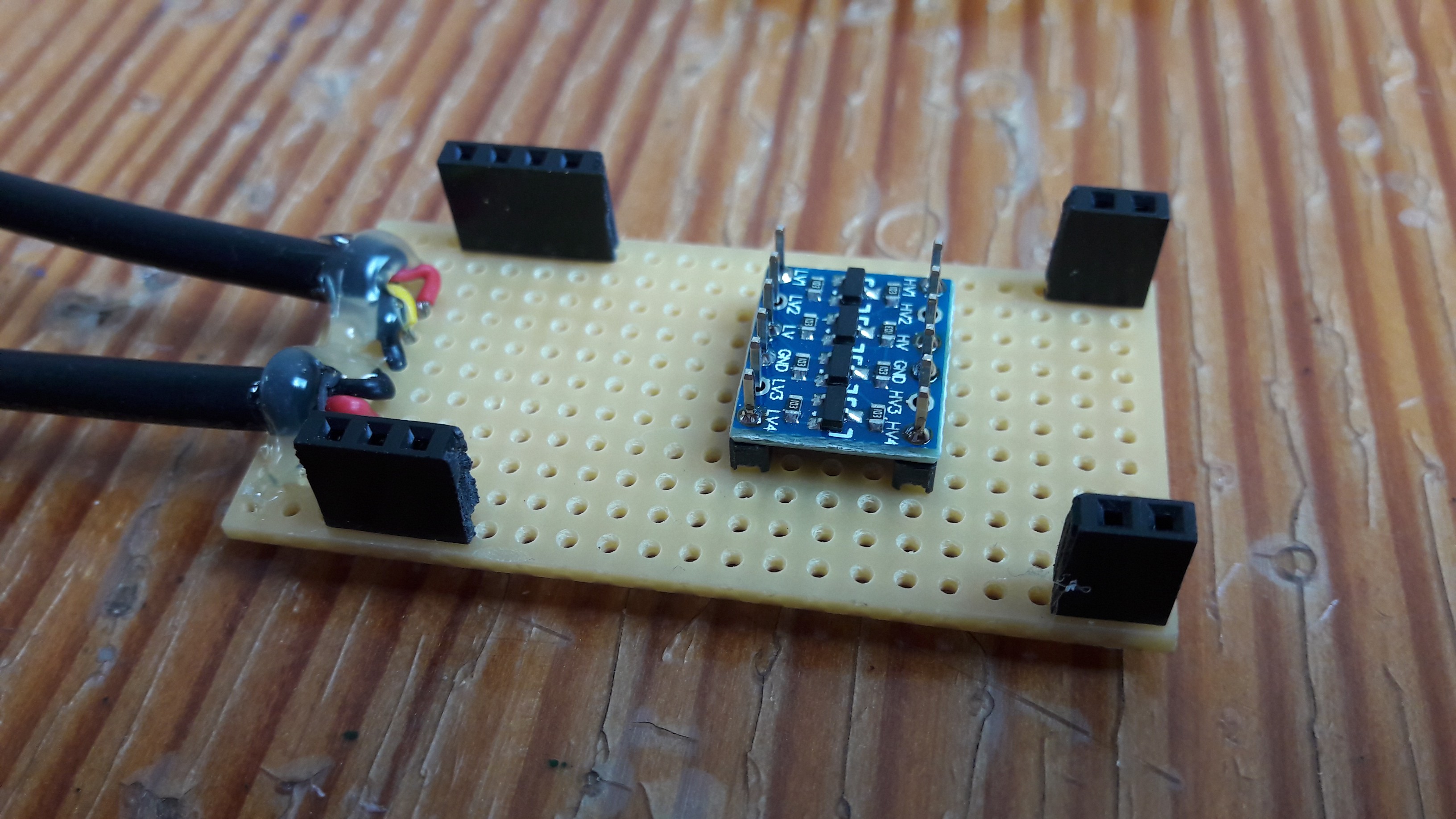
I use a basic ESP32 with BLE abilities mounted on a PCB like this :

The ESP 32 runs at 3,3V, so I'm feeding the 5V input PIN.
Ground will be grounded !
As the pulse is a 5V signal, you need also a simple level shifter. It's a 4 ways shifter but it was all what I had.
The shifter is located under the ESP :
On the left you can see the 2 wires : one goes to the CARDIO input, the another one is the LED that goes to a hole drilled on the side of the screen.
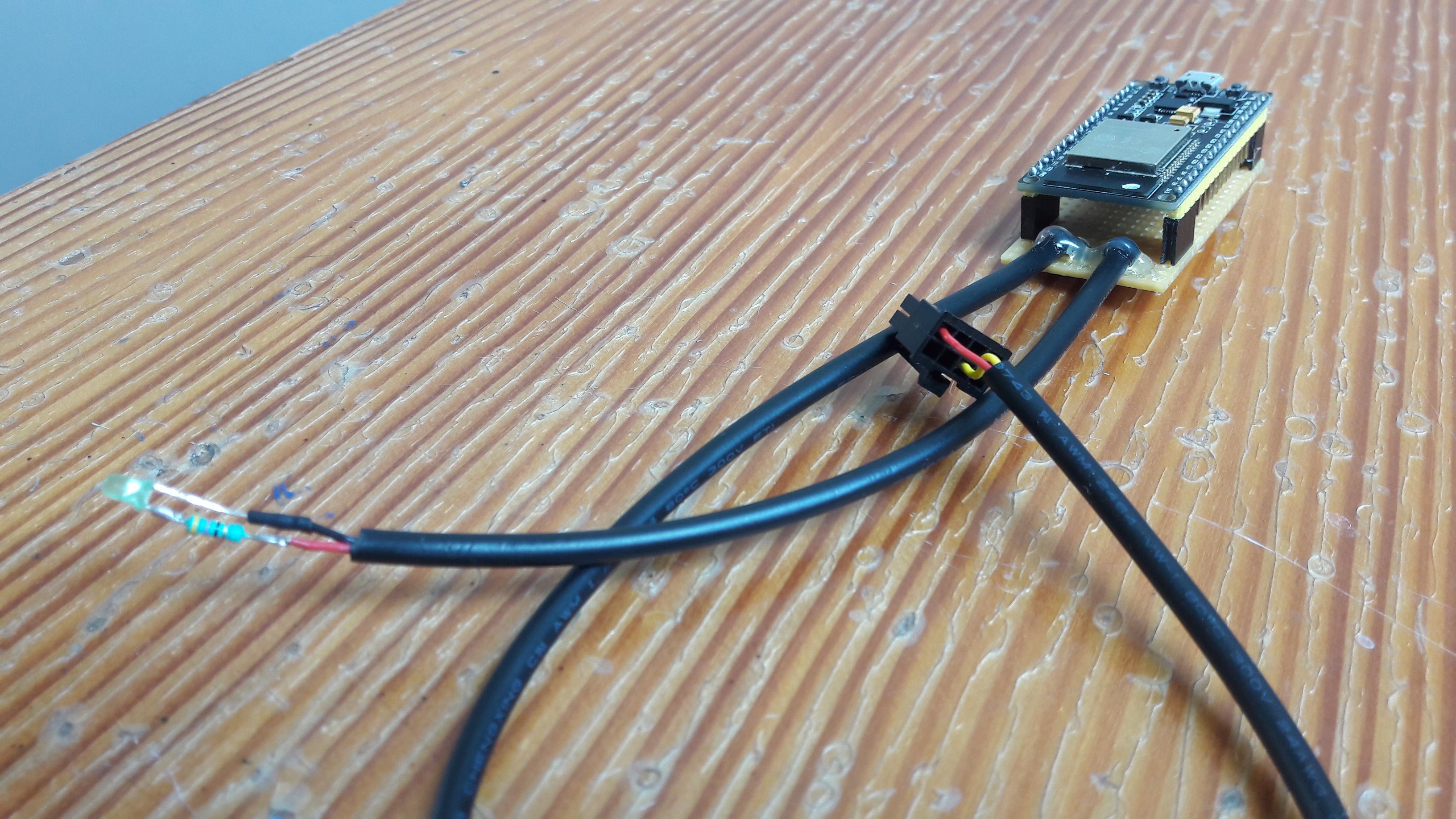
Wiring the LED with the less than 100R resistor.
6. Wiring
Since the Technogym has only 3 active pins
on a 8 pin connextor, you can directly connect the ESP32 with a proper connector to the Technogym main PCB.
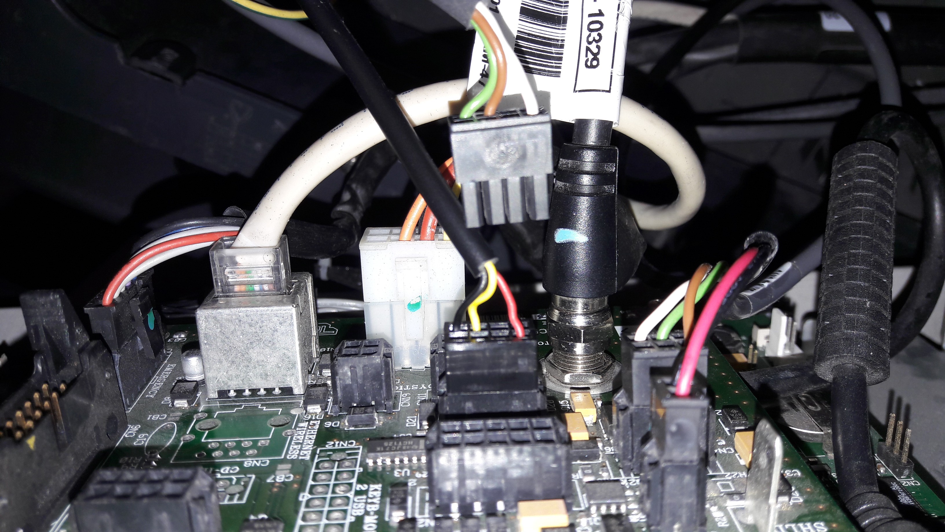
Locate the connector labeled "CARDIO" on the PCB behind attached to the screen. Watch out, you may see a couple af connector labeled "CARDIO" (8 PIN). There is a 6 PIN connector for the Heart Rate pads.
According to the Technogym connector wiring diagram attached.
PIN 1 : 5V (outpout from PCB)
PIN 5 : Ground (outpout from PCB)
PIN 6 : Pulse (input to the PCB) <- 5 V pulse
Here the connector I've removed (Brown, green and white wires) and new one connected.
7.Box
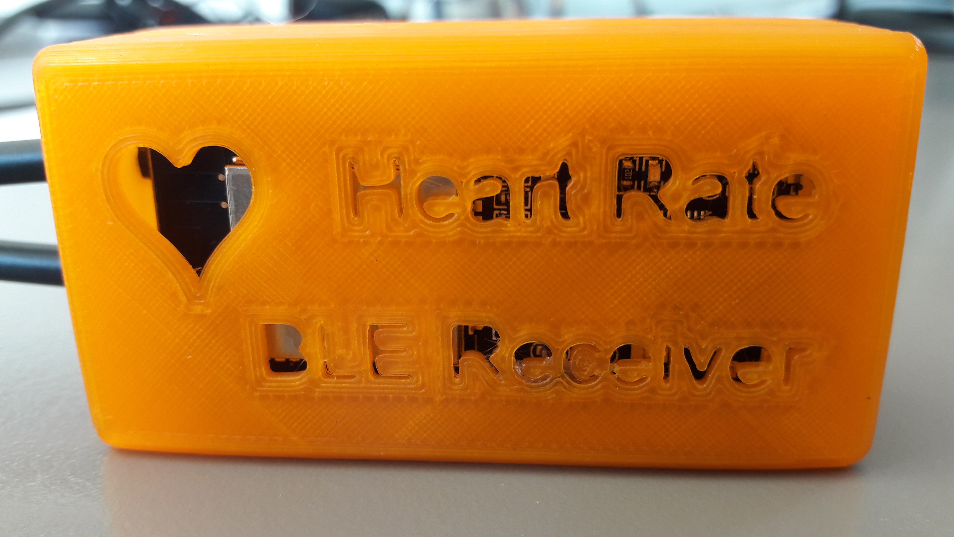
You can find the link to my box here :
https://www.thingiverse.com/thing:2859886
8. Conclusions
The BLE Heart Rate works well. You don't have to buy no longer the RF sensors each time the battery is under the weather. And cherry on the cake, you can monitor the battery level.
Enjoy.