 Eric Hertz
Alright, so it was stupid, stupid, stupid of me...
Apparently at some point (yes I remember doing this, no I don't remember *leaving* it this way) I modified the script that outputs the commands to the motor-driver... To: instead of outputting raw binary for positional-changes, instead output user-friendly hex-values. I just wanted to verify the conversion was working properly (this is a bash script). Brilliant, right? Wrong. Yeah, don't forget to comment-out that line when you're using redirection ('>') for the script's output to the serial-port!
So, simply, the motor-driver takes a single-byte value, -128 to 127, which tells it how many steps to take... And of course the "user-friendly" version was outputting several ASCII bytes... which, of course, are *positive*. Thus, the motor was going both *positive* regardless of what value I gave it, AND went *really far* each time (a sum of all the bytes transmitted).
Duh. No more redirection of binary values. Use two separate output-streams, one for the terminal, one for the serial-port. This realization came *long* after looking into all sorts of other things... including some amount of certainty that the uC's R/C oscillator was drifting too much for my 4800baud serial transmission... (seriously?!). Well, my de-facto for all projects is to have a fading LED that cycles at a rate of 8 seconds... I measured 7.3. That's pretty far off, so completely reasonable it might've been responsible. So I popped the ol' scope on the serial signals and realized that my new USB->Serial converter is 3.3V, and I'd already determined that my uC's VIH-min is 3.5V... so... well it did work a few days ago, but probably isn't particularly reliable. But the data-timing...? Looks pretty durn accurate to me, certainly not a full bit off (which would cause the "stop" bit to be detected as a '1' in the most-significant data-bit, which might've explained the large motion... except that the MSB is the *sign* so... I dunno.). And of course, that's when I noticed it was transmitting *several* bytes at a time...
Back to the old USB->Serial converter, also. At least I know its inputs are 5V-tolerant (I added that long ago).
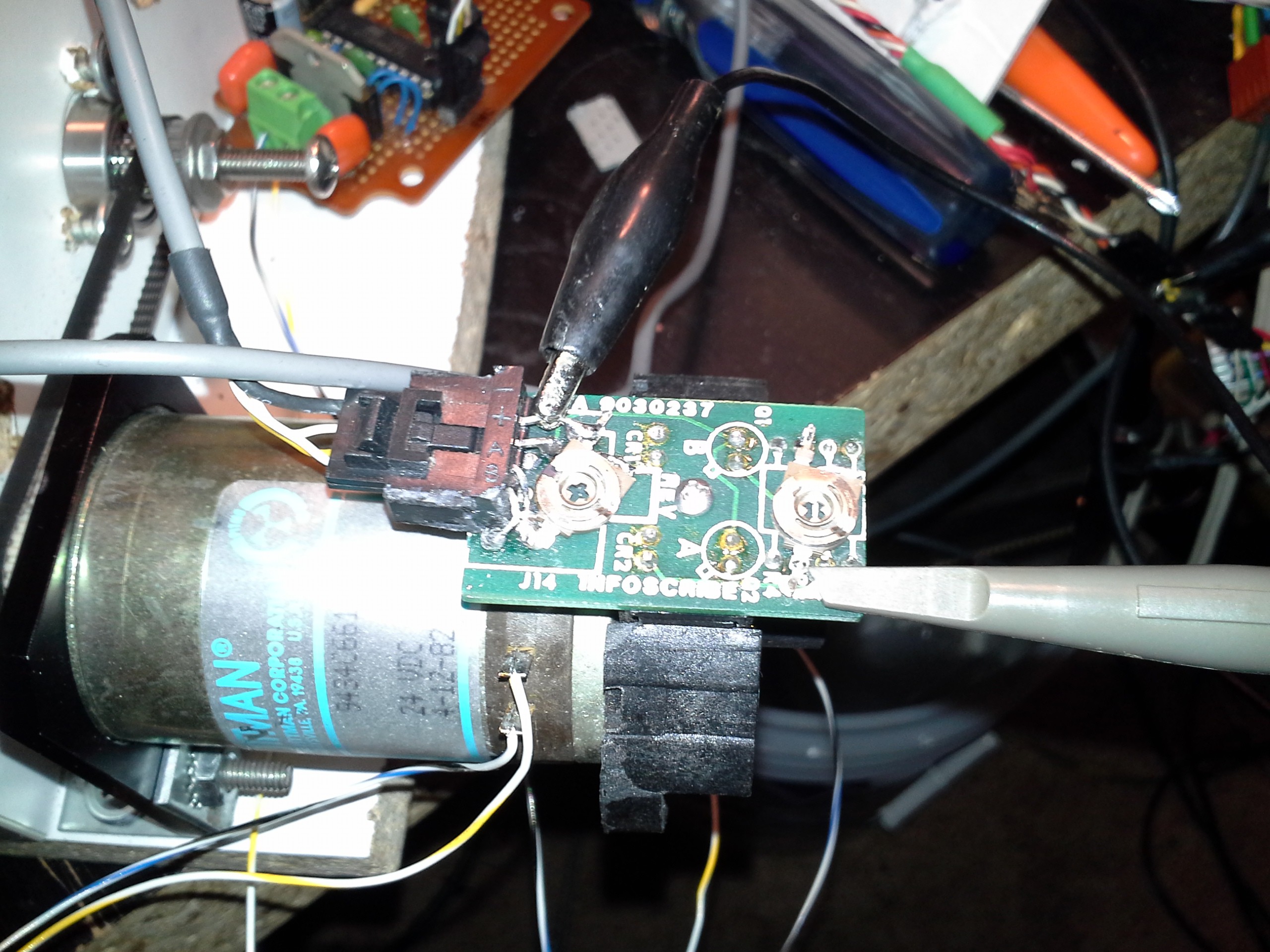
Oh, right, and the transistor-biasing issue... @K.C. Lee to the rescue again... I got all hung-up on trying to figure out a versatile solution, but wasn't getting anywhere. He suggests: just replace them dang 3.3k pull-down resistors with something higher, dagnabbit! So, I needed to see this thing moving again, dagnabbit! I cut them dang 3.3ks out of the circuit and soldered on some 20k potentiometers (and removed my transistor-buffer circuit entirely).
So, some observations: With the mouse-encoders I'd worked with previously, there seems to be some correlation with the pull-resistor values and the *speed* the transistors can respond. A higher value resistor, if I remember correctly, results in *slower* response. My theory being somewhat like that of the difference between ECL and TTL... ECL is faster than TTL because it keeps the transistors AWAY FROM saturation (ECL uses the linear range), Switching out of saturation takes time. Anyways, that's not (yet?) a problem here, since the motor's running *much slower* than the really-high-speed motors I had connected to the mouse-encoders.
Increasing the resistance essentially increases the "amplification" of the signal... so whereas before it was somewhat sinusoidal, now it's closer to digital... rather, it's like an amplifier hitting its (upper) rail... There's still analog changes as the motor is rotated slowly between slot and shade(?), and it also appears to remain sinusoidal-ish at the lower-rail.
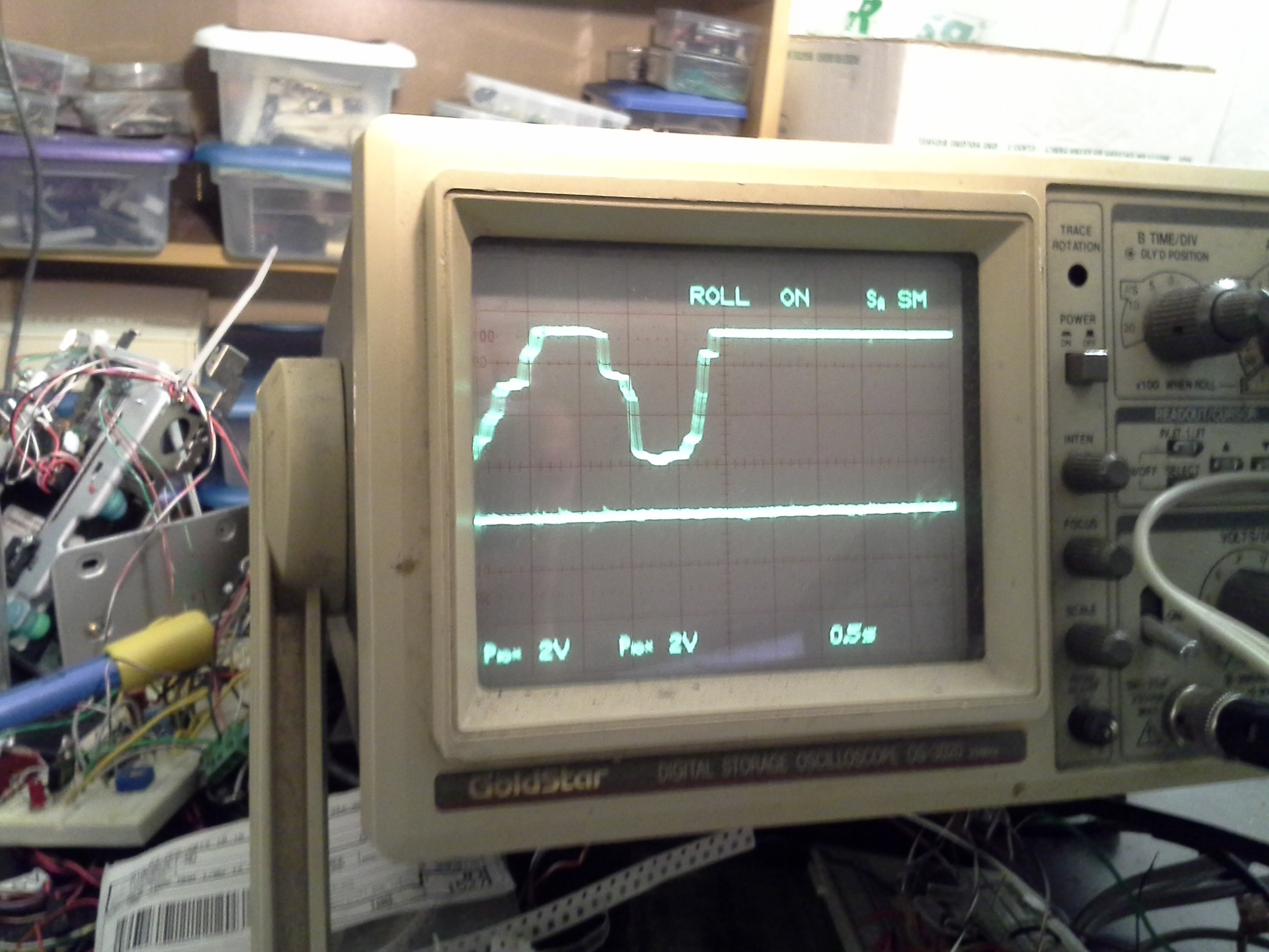
Thankfully, my microcontroller has Schmitt-triggers, and the system's now definitely within the VIHmin and VILmax ranges, so it seems alright. Though, I'm not certain the "threshold" is particularly well-defined... Imagine a sine-wave amplified *a lot*, with its bottom touching 0V and hitting the upper rail (5V) long before the sine-wave reaches its zero-crossing... Rather'n *square* pulses, I might be getting really skinny rectangles. As long as both quadrature channels keep those rectangles *in quadrature* then it's no problem except that it means the positional accuracy varies at two of the four measurable points in a quadrature-cycle... Something to ponder, but doesn't seem to have a noticeable effect.
As far as the PWM noise coupling in...? It might still be, I haven't 'scoped the receiving-end... But it's no longer going through my transistor "amplifiers" (and the cable is now shielded) so it should be a little more immune. It seems to be working fine!
Well, fine on the electronics-side... the mechanics are... built by me, with my tools and my supplies... At the very least, I think I need to oil this thing... Cooking-oil seemed to work great for tapping and drilling, but it gets kinda gummy and smelly after a while. Best buy some motor oil (will that be any better? This isn't a closed system... And WD-40 is a solvent, right? Not for long-term "oiling"?).
Discussions
Become a Hackaday.io Member
Create an account to leave a comment. Already have an account? Log In.
It has passive pull down, so the discharge (i.e. from H->L) time constant is R*C where C is the stray capacitance which is dominate by cable capacitance. You can play around with the trim pot to a lower R value and have just enough amplitude for VIH(min) or use a shorter cable or a lower capacitance (i.e. a twist pair instead of coax). As long as the motor isn't spinning too fast and you use the rising edge for timing, you are okay.
There are ways of making a push-pull driver out of that opto output. Let me know if that's what you want.
Are you sure? yes | no