 dave
daveNow as you can see from the pictures I am not very good at making neat items. In this case I will justify some of the sloppiness by saying “that’s almost how the original looked” but hey its neater than mine. Any way drilling the 40 holes for the typewriter buttons was a challenge.
A quick aside, only 32 of the buttons are used, but they had experimented with different store widths, and the follow on machine, the Manchester Mk1 had a 40-bit store. So at the time it ran its first program it is believed that the Baby had 30 buttons on the Typewriter even though only 32 were used.
Any way back to drilling the holes. My first thought was to make a template from Vero Boards (or other PerfBoard) as these have holes on a 0.1” spacing and so make a great template. However, initial experiments were a total disaster. The vero is so weakened by all the holes it just fell apart as I used it.
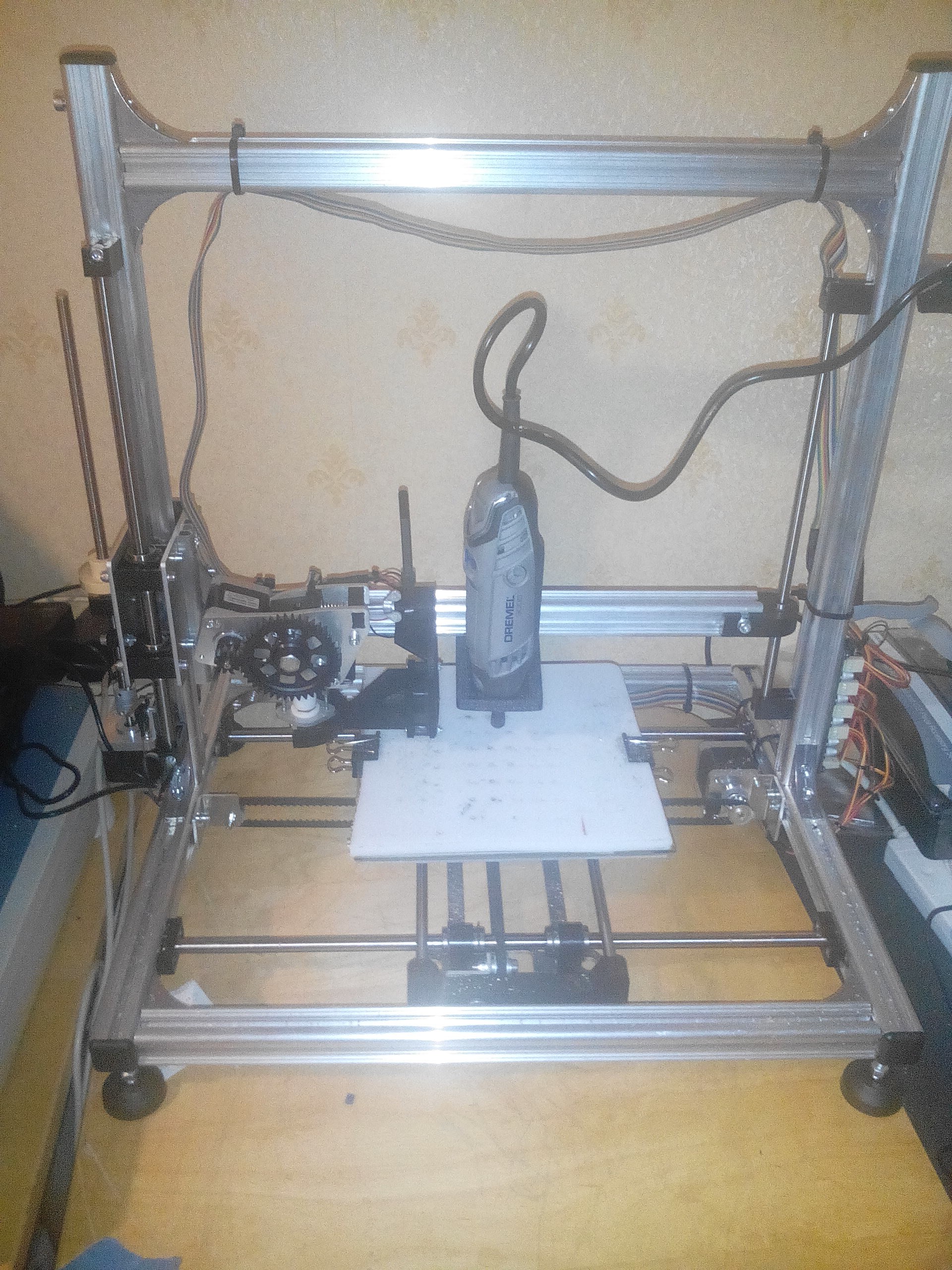
Now I do own a Velleman K8200 3-D printer
http://www.velleman.eu/products/view/?id=412554
which is a basically the same as the RepRap 3Drag.
and I know that folks have adapted the model I own to do PCB milling and drilling. It therefore seemed that as all I wanted to do was drill 40 holes it should be a trivial task. The instructions on this modification are here:-
http://www.open-electronics.org/how-to-transform-your-3drag-3d-printer-in-a-cnc-milling-machine/
so I thought great, follow the clues and I can drill the hols like a PCB. If only the world was so simple! The first hurdle was the Proxxon Drill they use. Its available in the UK but is very expensive, and I already owned a Dremel which is a very similar tool. However, the Dremel will not fit in the Proxxon collar. Actually this was the simplest thing to fix. A quick search of the “Thingyverse” turned up a Dremel mount for the K8200:-
http://www.thingiverse.com/thing:388701
and after two or three attempts at printing I had one mounted on my printer….
… then the fun began….
How to tell the printer where to draw the holes? This article: -
http://www.open-electronics.org/3drag-as-a-cnc-milling-machine-creating-g-code-via-eagle-software/
After some investigation I found this tool “CamBam”.
Great I thought, GCODE out, I can feed it straight into the printer. So I sketched up a grid of holes, ran it through the printer, which moved the head around and didn’t drill any holes. What on earth was going on! Time to learn GCODE!
Actually GCODE is pretty simple. Each line has a GCODE function at the start followed by parameters, so
G1 X1 Y1 Z1
Says move the tool head to the point X=1, Y=1, Z1. There is more information here:-
https://en.wikipedia.org/wiki/G-code
Now the problem I had was that CamBam out puts GCODE “G81” which says “drill a hole” and the 3D-Printer does not understand how to drill holes, even with the modified firmware installed. In the end I wrote a small VB program to convert the G81 codes into a series of “G1” codes
So finally I could drill my holes, not all at once, as the print bed isn’t big enough, but he we got it done….
Discussions
Become a Hackaday.io Member
Create an account to leave a comment. Already have an account? Log In.
For such a little project as well :-)
Are you sure? yes | no
Ah the adventures :-)
Are you sure? yes | no