 Laetitia BEL
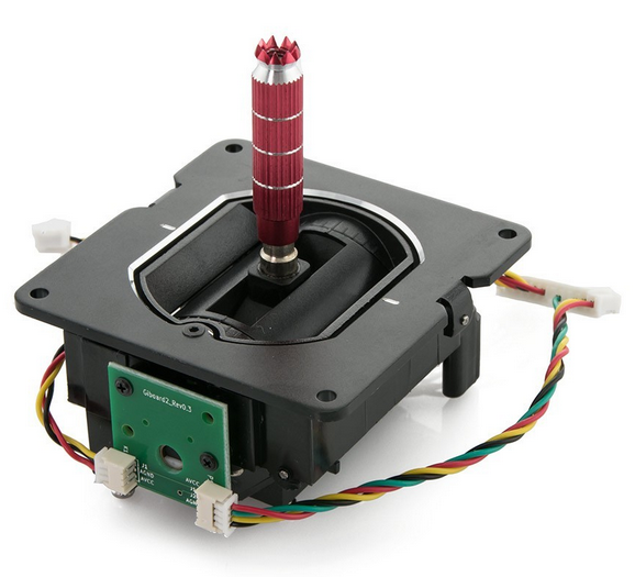
The analog joysticks that will be used are the same replacement for Fr'sky ones
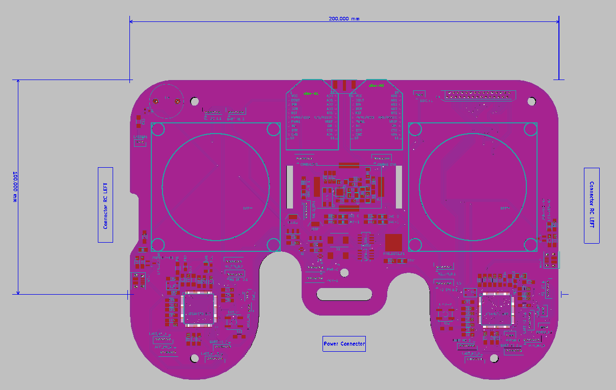
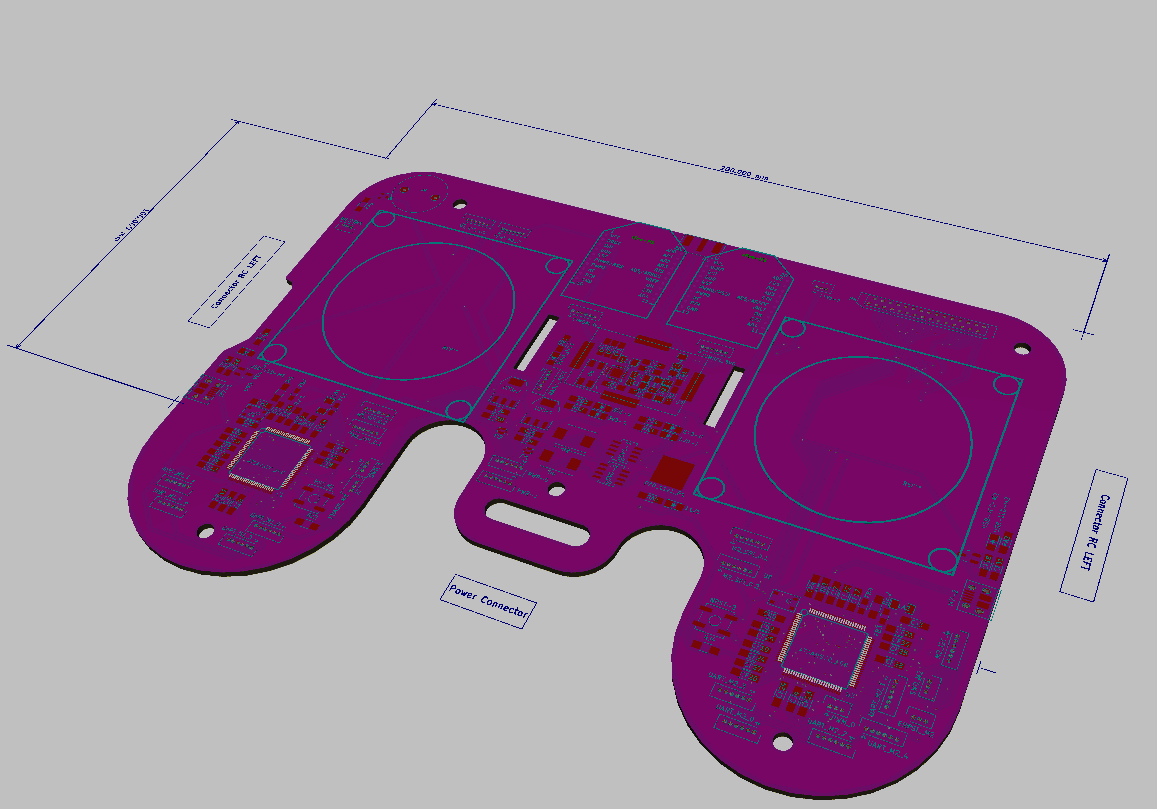
The PCB of the remote controller has changed a little bit.
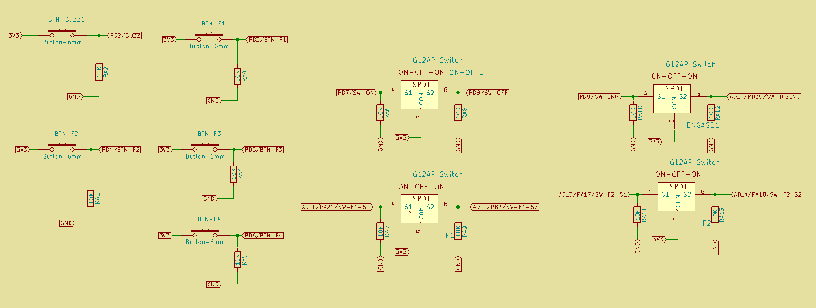
The TOP PCB will hold the analog sticks, buttons and leds.
I added the possibility to fix a LCD, I don't know yet which.
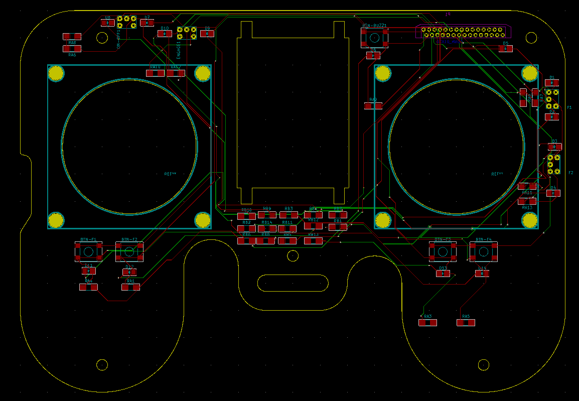
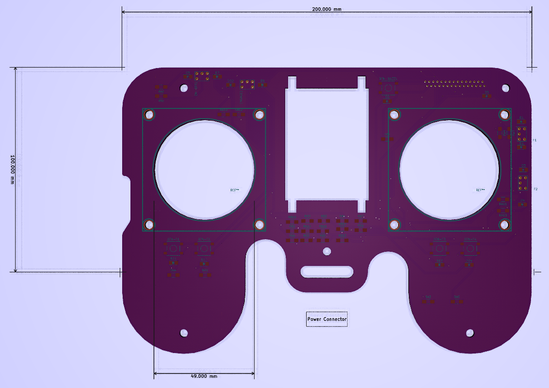
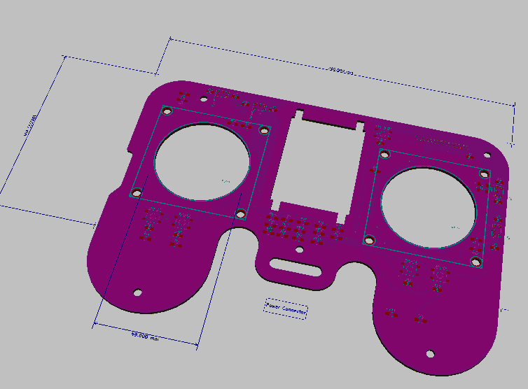
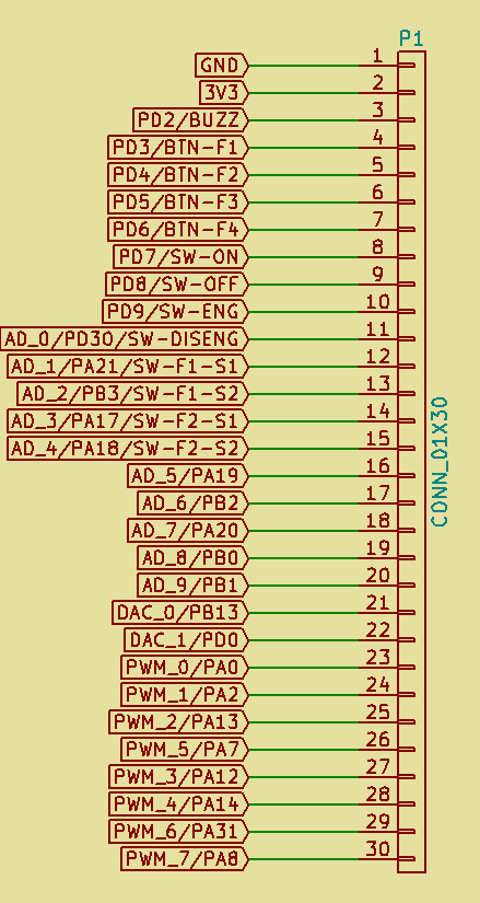
The link between the TOP and BOTTOM PCB of the remote controller is done using a PFC connector with 30pins (finally).
I added both tactile buttons and small rockers.
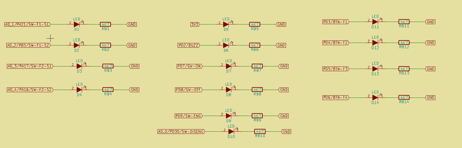
There are a bench of LEDs to displays statuses.
REMOTE CONTROLLER PCB BOTTOM:
The bottom PCB will hold the micro controllers and all the circuitry relative to the power.
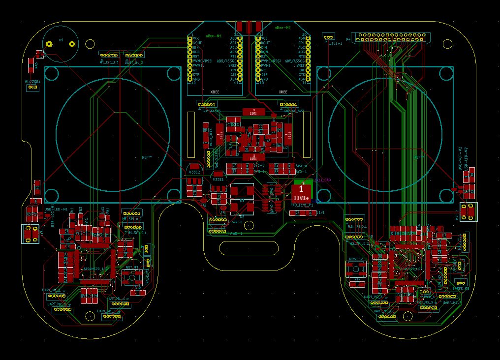
The funny and interesting thing is that the same components used in the flying part are used in the remote controlled.
The idea is to have the same configuration to ease the software development and also for me to have the same circuits.
It might appear that the remote controller has more calculation power that it will require, but whynot.
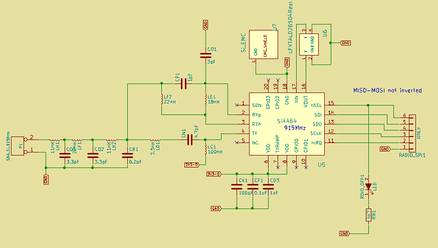
We use the same Si4464 communication module with SMA antena:
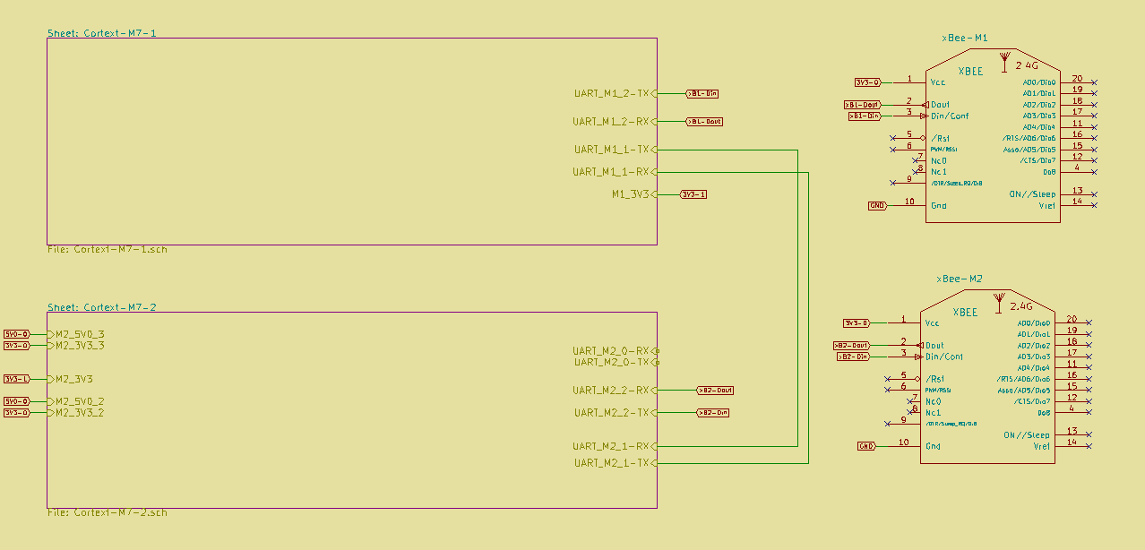
We use two xBees, and the SAME70-R1/R2 are linked using an UART:
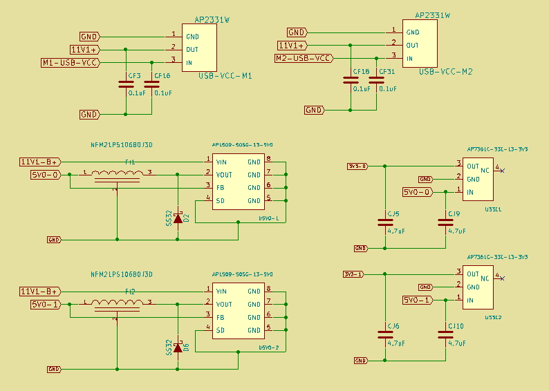
We use the same DC converters, but not the same number, because the need is not the same:
Discussions
Become a Hackaday.io Member
Create an account to leave a comment. Already have an account? Log In.