So after I made the daughter board for the STM32F411 Nucleo, I started thinking, I wonder how hard it would be to create my own minimal STM32F411 board? So I started looking at minimal circuits online and at ST's documentation. From what I saw, it wasn't too bad! Mostly a bunch of decoupling caps, as well as a voltage regulator with caps, and crystals with caps!
But one of the aspects of the chip though is how to program it? So reading about STM32F4 chips I found that they come with a hardware bootloader that allows programming over the serial port! But in order to program the STM32 this way, there is one pin (boot0), that you need to toggle when powering on the chip in order to boot the chip into programming mode. I wanted to be able to program the chip wirelessly with the cheap and widely available HC05 module. But what a waste it would be if I could program the board remotely, but had to walk over to my robot and toggle it into programming mode and back again. How could I toggle that pin remotely?
After researching and trying to find a bluetooth module that could do this, I found Adafruit's bluetooth module that claims it can toggle an output pin in addition to the serial pins. But Adafruit's module is much more costly than the inexpensive HC05 boards. So I tried thinking about another solution. What if I threw a cheap 8 pin avr onto my board to monitor the serial port and toggle boot0 when it saw a certain serial command over the
line. So I threw a attiny13 onto my schematic and hooked it up to monitor the serial port and toggle boot0. Wanting to keep the board cheap, I picked the cheapest attiny I could. So it didn't have hardware serial support. I also didn't want to have to put a crystal on the board to minimize the part count and cost, but could I reliably detect a serial command without a crystal? I figured since I didn't need to have a complete serial library, all I needed to do was to monitor the line for a small handful of commands. I realized that if my commands are premade to never have more than two of the same bits in a row, any error due to the clock is minimized! In other words, if your clock has a 15% error, it is really difficult (impossible) to tell 7 zeros in a row from 8 zeros in a row. But if you know that all your signals never have more than three same bits in a row, you can easily tolerate quite a high clock error and still reliably detect messages. So I wrote my own arduino code to look for signals that I came up with that have minimal bit switches (like "resetSTM32" and "writeSTM32"). I wrote a C program to generate the bit-string representations of the codes and hoped it would work! In other words, the arduino program does look for "resetSTM32", but rather for {0x12, 0x32, 0xF2, 0x11, 0x11, 0x22, 0xF2, 0x21, 0x32, 0xF1, 0x11, 0x11, 0x22, 0xF2, 0x13, 0x31, 0xF2, 0x21, 0x12, 0x11, 0xF2, 0x13, 0x11, 0x11, 0xF1, 0x11, 0x21, 0x12, 0xF2, 0x21, 0x22, 0xF3} where every four bits represents how many bits in a row stay the same (including the start bit) and an 'F' is a special code that means to ignore the number of stop bits!
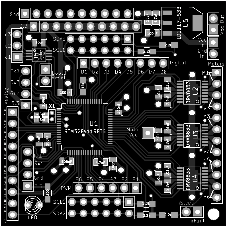
Next I arranged all the pins to be easily accessible, put the DRV8833 motor driver chips onto my board, the voltage regulator, all the caps, and this was the result:
Off to the board house. When the boards came back it was time to try to solder the LQFP64! So I went to youtube to try to figure out how to solder surface mount chips. I have done lots of through-hold soldering over the years, but this was my very first attempt at SMT soldering.
So I got a recommended tip and tried the drag soldering technique. I tried and tried and tried and never got good results. Solder bridges everywhere. I'm sure I eventually could have figured out how to do it, other people apparently have perfected the technique. But I decided to try something else. So I ordered a $20 skillet, solder paste, syringes, syringe tips, isopropol alcohol, and decided to try to reflow my board.
After spending time experimenting with tips, I found a tip size that seemed to give a good sized bead of solder across the pins of the LQFP64. I threw it on the skillet to see how it would come out. Not bad! I kept experimenting until I got the hang of how much solder to lay across the pads. Then a little work with a solder wick and it looked like all the pins on the LQFP64 were soldered! Next I put solder on the rest of the SMT pads
and put the board back on the skillet and reflowed it again. It looked like everything was good! Next I did all the through-hole part with my iron and tried to see if I could get the board to boot up!
My goal was to be able to program the board over the serial port. But after much trying, I couldn't get stm32flash to detect the chip. I was able to use the STM32F11 Nucleo board as a programmer though. This is a very useful aspect of this board. It has a board perforation that separates the programmer from the simple STM32F4 circuit. So I could break the perforation and use part of it as a programmer. I was able to program my board! So my circuit worked! This was a huge moment for me :)
But why wouldn't programming over the serial port work. I finally realized that not every serial port on STM32 can be used with the built-in bootloader firmware! Deep in the ST docs you can see which specific serial port pins can work with the bootloader. In fact, on my chip, there are only two specific pins that can be used for the serial bootloader, and I hadn't brought them out to the serial port! I was able to hook them up anyway and finally get stm32flash to find my board using a USB to serial cable!
Success!!!
Discussions
Become a Hackaday.io Member
Create an account to leave a comment. Already have an account? Log In.