 Keith Elliott
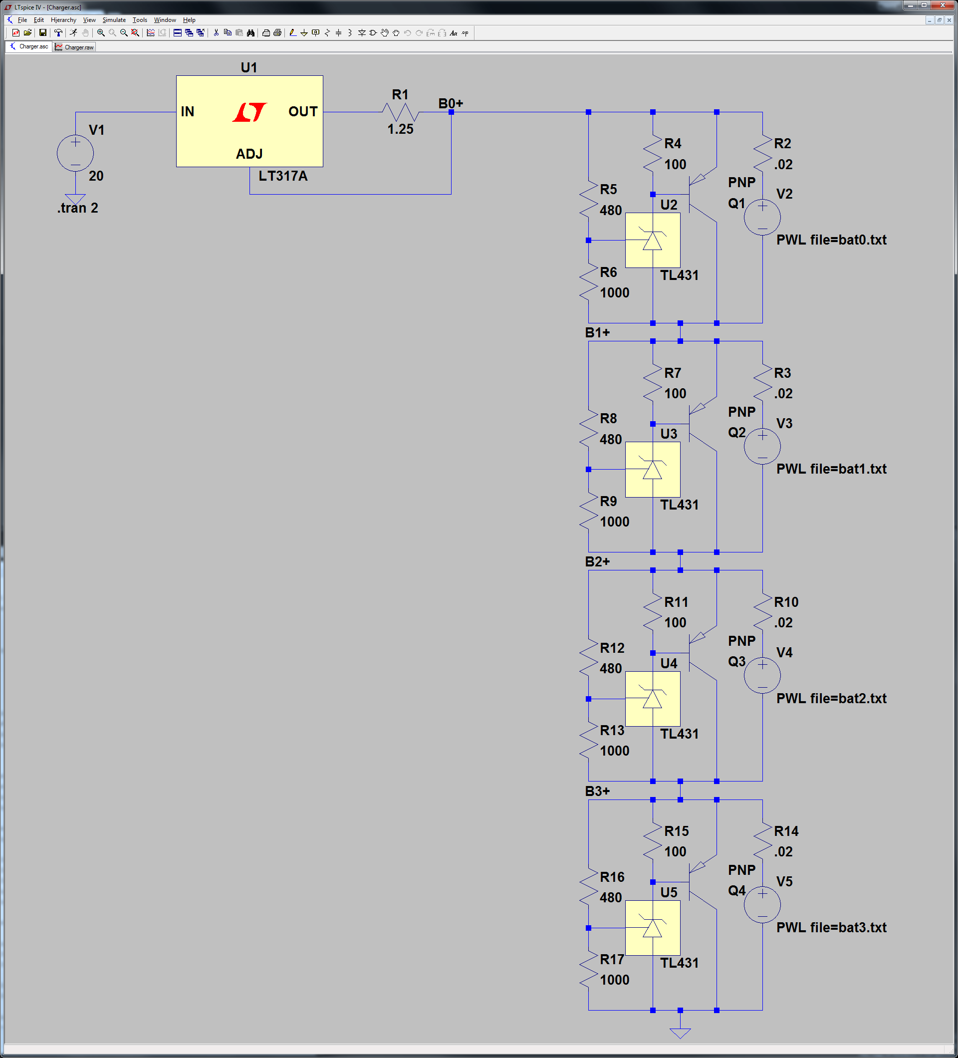
Since I decided to use a 4S LiFePO4 battery in my previous post, I’ve been looking online for charger design resources and examples. From what I gathered from several sources, I’ve come up with what I think is a circuit that will work for charging the LiFePO4 batteries. Before I go into the details of the circuit, however, let me briefly cover the basics of LiFePO4 charging.
LiFePO4 Charging Basics
Most of what I learned about LiFePO4 charging comes from this article which goes into great detail about the charging specifics, but which I’ll summarize here for the sake of brevity. LiFePO4 uses what’s called CC/CV, or constant-current/constant-voltage, charging. This means that a constant amount of current is supplied to the battery when charging begins, with the charger increasing or decreasing the supplied voltage to maintain the constant current. Once the battery reaches a certain voltage, 3.65V in the case of LiFePO4 batteries, the constant-current phase stops and the charger supplies a constant voltage to the battery. As the battery gets closer to fully charged, it draws less current until it’s full.
Constant-Current Circuit

The constant-current circuit was easy enough. The popular LM317 regulator has a constant-current configuration, shown by Figure 19 in this PDF. Based on the equation in the attached PDF diagram, a 1.25 Ohm power resistor would result in 1A of constant current.
Constant-Voltage Circuit
The constant-voltage circuit was a little more complicated to design. The difficulty with supplying a voltage to four batteries simultaneously is that the voltage needs to be evenly distributed to each of the batteries. This is called cell balancing. Without it, one battery may charge faster than the others, resulting in a larger voltage drop across that particular cell. As the battery pack becomes more charged, the individual cells will become more unbalanced, resulting in wasted energy and decreased performance. Once I took this into account, I realized I needed to both keep a consistent voltage across the battery terminals, and redirect current away from the battery when it had completed charging so that the other batteries could finish charging as well.
With this in mind I looked into using Zener diodes. These operate like regular diodes by only allowing current to travel in one direction, up to a certain point. Unlike regular diodes, however, they allow current to travel in reverse when a threshold voltage is exceeded. They’re commonly used in power supplies to prevent voltage spikes. When there’s a spike in voltage that exceeds the threshold, the Zener starts conducting and acts as a short circuit, preventing the voltage spike from affecting the rest of the circuit. The problem with Zeners, as outlined in this post, is that they have a “soft knee” with a slow transition to conductance around the threshold voltage. This results in inaccuracies in the threshold voltage required for the Zener to conduct, making it too inconsistent to use as a voltage limiter.
Luckily that posts outlines an alternative. The TL431 acts like a Zener diode, but has a much sharper curve and a programmable voltage threshold. By using a voltage divider with a potentiometer, it’s possible to tune the TL431 circuit to conduct at exactly the desired voltage.

Above is the circuit I implemented. Because the TL431 has a maximum current rating of 100 mA, I opted to use a PNP transistor as an amplifier. When the threshold voltage of 3.65V is exceeded the TL431 conducts, turning on the PNP transistor and providing a short circuit to route current around the battery cell. The complete charger is made up of four of these circuits in series with the high side connected to the constant-current circuit discussed above.
Improvements
Once I’ve verified that this circuit works and properly charges a battery, there are a few things I’d like to eventually go back and add to this circuit. The first is an undervoltage detection circuit. Lithium rechargeable batteries become useless if they’re ever fully discharged. This full discharge can be prevented by cutting off the power from the batteries before they reach the absolute minimum cell voltage. This is ~2V in the case of LiFePO4 cells. A circuit similar to the one for maximum voltage detection could be used to check for the minimum voltage and disconnect the cells, preventing permanent damage to the battery pack.
I’d also like to add an output for the total battery pack voltage so a microcontroller can measure and detect the state of charge for the pack. This would involve using a voltage divider to provide a divided down voltage within the measurement range of standard microcontrollers.
Next Steps
I drew up the circuit schematic described above in LTSpice, a free circuit simulation tool. Despite LiFePO4 batteries being safer than LiPos, I’m still erring on the side of caution and will check my work every step of the way. Simulation seems like the next best option to actually testing a physical circuit. My next update will outline my simulation parameters and the results I saw.
Discussions
Become a Hackaday.io Member
Create an account to leave a comment. Already have an account? Log In.