 Keith Elliott
After tons of design work and hours of printing, the prototype for the navigation chassis is done! This is by no means meant to be a final version, but rather will serve as a prototyping platform to start work on the electronics and software for the robot. Pictures and explanations are below!
Components
DesignDue to print bed limitations I divided the navigation unit of the robot into three main sections, two motor sections and a front section. Each of these sections was then split in half for printing. There are mounting holes on each part that allow everything to be assembled using M3 nuts and bolts.
In terms of sizing I’ve left a 150mm square at the center of the robot as well as the back quarter of the circle as free space. These should provide sufficient space for any extensions I design.
Motor Assembly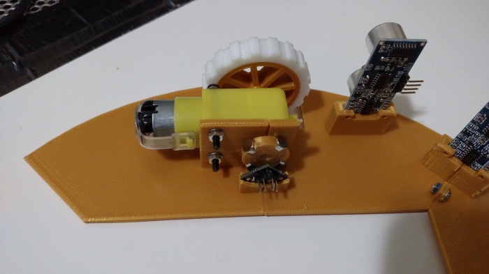
The motor assembly is the most complex part of the design, consisting of five separate parts. For the motors I decided to use the most common motor found on eBay, a generic yellow robot motor. They tend to be very cheap and easy to use. They’re attached to the motor mount using M3 nuts and bolts.

While these motors usually come with wheels, I found them to be too large and cumbersome. Smaller wheels were necessary to conserve space so I designed simple, 3D printed ones using a spoked hub and TPU filament for the tires to provide traction.
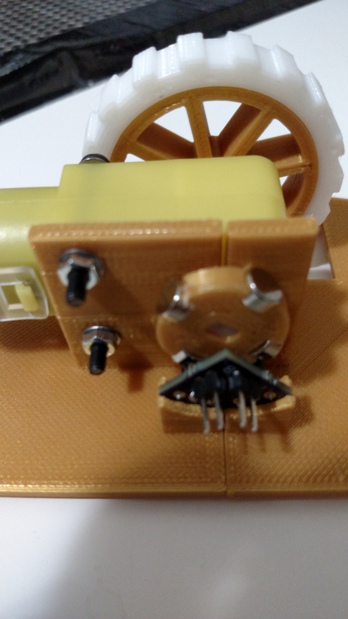
I couldn’t find any cheap encoders that I was happy with on eBay, so I decided to design my own using magnets and hall effect sensors. The magnets are generic 1/4 in. and should be easy to find. My reasoning behind using magnetic encoders instead of optical is because magnetic encoders tend to be more robust when it comes to dirty environments. I’ll go into detail about the hall effect sensor PCB I designed when I do a write-up for the electronics.
Ultrasonic Rangefinders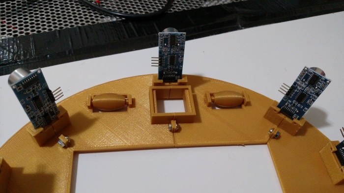
As seen in the top image, I have five ultrasonic rangefinders that will be used for localization and mapping. They’re mounted on either side, in the front, and 45 degrees to the left and right of the front. This will provide the robot with a full view of obstacles in front of the robot.
Color Sensor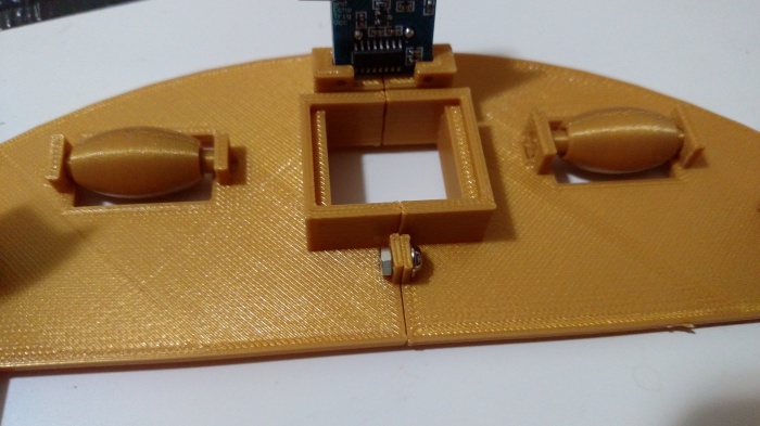
I’m still waiting for this part in the mail, but I’ve designed space for a TCS3200 color sensor module. This will be used for determining what type of floor the vacuum is on. This color sensor uses internal photodiodes to measure the amount of reflected red, green, blue, and white light. I’m hoping that I’ll be able to use the white light magnitudinal component as a primitive proximity sensor so the robot can detect stairs.
Casters
Rather than using metal ball casters like I was originally planning, I decided on designing 3D printed rollers instead. These are the same type of casters used on the Neato robots.
BumpersWhile I have yet to design in the bumpers for the robot, I plan on usingmicroswitches attached to two 3D printed front bumpers to detect obstacles, on bumper on the front left and one on the front right.
Improvements
There are a handful of things that I’d like to tweak to improve upon this design. The current version of the navigation unit only has 3.5mm of ground clearance. I’ll be playing with this a lot in order to strike a balance so that the cleaning module is low enough to optimally clean the floor, yet high enough so the chassis doesn’t sag and drag on the ground.
While I’m currently using five ultrasonic sensors, I’m unsure as to whether that many is needed, or if the mapping will be fine with only three. I’d like to remove any unnecessary components to cut costs.
There are a few other difficulties I noticed when assembling the navigation unit. Mounting the wheel on the motor proved a little difficult due to the size of the wheel well. Since I have some extra space I’ll probably increase the well size to make mounting the wheel easier. The same goes for the casters. Because the axle can’t be 3D printed with the chassis design, I have to find a way to mount it on the front that allows it to be put in easily but doesn’t allow it to be knocked out during use.
As always my design files are available on the Github repository. Thoughts, comments, and criticism are always welcome. I’ll be doing a lot of tweaks on the design and wiring up the electronics in the near future. I hope to do a full electronics write-up soon.
Discussions
Become a Hackaday.io Member
Create an account to leave a comment. Already have an account? Log In.