 Russell Cameron
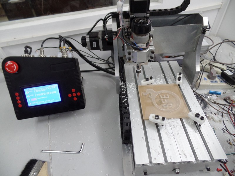
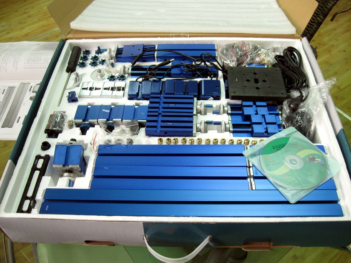
This project began several years ago when I got a multi purpose machine kit. The kit allowed you to build various machines including a lathe and milling machine. Obviously I wanted to automate the kit but I knew nothing about CNC or CAM software.
Most hobbyist CNC machines seem to use Mach3 software and a parallel port interface to control them but I wanted my machine to run without a computer attached. There are RAMPS PCBs that allow an Arduino to run a machine but I wanted to create something simpler for a complete novice who knows nothing about electronics.
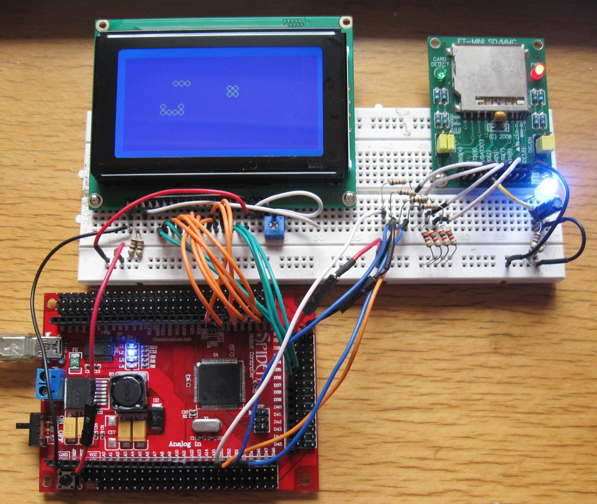
Im pretty good with electronics and had been learning to use Arduino so I decided to make my own stand alone controller. I started with a Spider controller, a T6963 240 x 128 LCD and an SD card socket. This setup allowed me to learn how to use the SD card and T6963 libraries. The LCD display includes a 6x8 character set which gives you a 40 x 16 text display. I did not bother with a fancier colour display since your not going to be spending much time looking at it except when you first set up the job.
Once I had the basics worked out (or at least I thought I had) I had a PCB made. This first prototype used Allegro A4988 stepper motor drivers which are supposed to be able to deliver up to 2A on each output.
The A4988 is a surface mount IC and really needs either heatsinks or a 4 layer PCB that uses the rear layer as a heatsink as shown in the datasheet to deliver the full 2A. I found I could not get more than about 1.5A before the chips started shutting down from thermal overload. I also discovered a problem with the way my hardware was scanning the buttons and limit switches.
When I designed the new controller I designed it so that the MCU I/O pins were grouped in a way that allowed the software to use port manipulation. This allowed the software to run much faster when controlling the motors and scanning the buttons / limit switches. It also gave me access to additional I/O pins that the Arduino software does not normally let you access.
At this point I should mention that I am one of those people who do not like unused I/O pins and in finding uses for the extra pins (such as monitoring motor fuses, thermal overload pins etc) I got a bit carried away and actually ran out! I had used 86 I/O pins and wanted more.
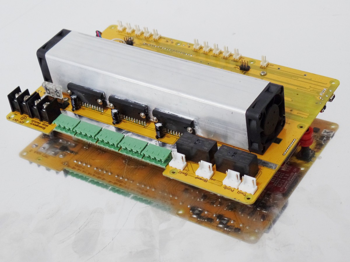
In the end I added an ATmega8A processor linked via the I²C bus. This processor is dedicated to spindle speed control and attempts to maintain a constant cutting tool speed as the load changes.It also gave me extra analog I/O pins to monitor air temperature, heatsink temperature and spindle motor current draw which can be used to detect a stalled motor.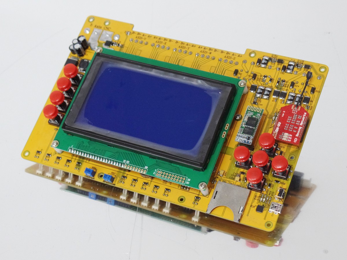
I used a tunnel heatsink which has cooling fins on the inside and two 40mm cooling fans, one at each end. Even if one fan dies, the other fan can prevent overheating until the fauly fan is replaced.
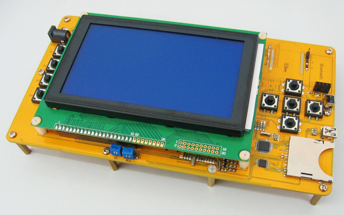
You may have noticed in the photos that I have added sockets for bluetooth and Xbee / WiFly modules. My intention was to allow wireless monitoring and g-code uploads. So far the g-code uploads have been a problem as the g-code needs to be written to the SD card. Unless the data is transfered at a painfully slow rate then chunks go missing. Until I find a solution to the problem the wireless features are only good for wireless control and sending information such as job status.
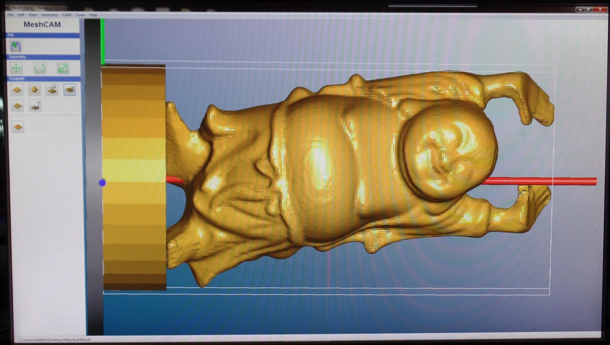
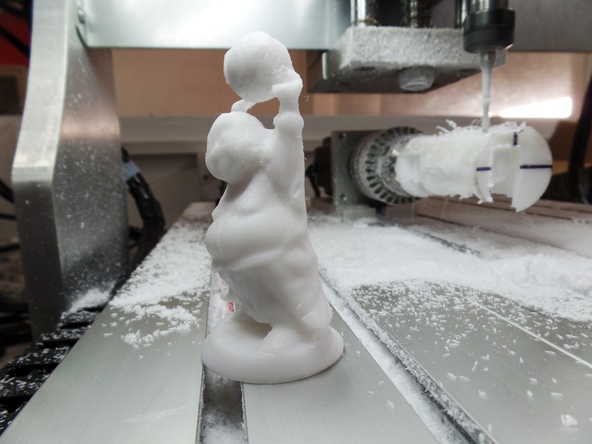
The controller hardware is finished and now I'm working on the software. I have one version for 3-axis machines and an experimental version for 4 axis. When I have time I will combine them. There is support for the 5th axis but currently I have no cam software that will generate 5 axis g-code for me to test with. Below is a Buddha statue I made while testing the 4th axis software using MeshCam to generate the g-code.
Hardware Specifications:
- Power: 12V - 36V, 25A maximum.
- 5x TB6560 stepper motor drivers rated at 3.5A each with current limiting and thermal overload protection.
- 2x 5A Spindle motor outputs (reversible) with current sensing, PTC fuses and blown fuse detection.
- 2x 2A coolant pump / blower outputs with PTC fuses and blown fuse detection.
- 240 x 128 LCD display.
- 5x home switch inputs.
- 5x limit switch inputs.
- 2x Spindle motor speed sensor inputs or 1 speed sensor and 1 touch sensor.
- Emergency stop cuts power to all motors.
- Security key lockout to prevent kids pressing the wrong button when your not looking.
- SD card socket.
- CP2102 USB interface for software updates / data transfer.
- Sockets for optional bluetooth and Xbee / WiFly modules.
- DS1307 real time clock.
- I²C bus broken out for both 5V and 3.3V devices - useful for adding additional hardware.
Software:
This is the hardest part for me and it's still not finished yet. I have never used a CNC machine or 3D printer before so I started this project with no knowledge of CNC machines, cam software or g-code. I have tried to use my lack of experience to keep things as simple as possible for other beginners. All the software has been written using the Arduino IDE.
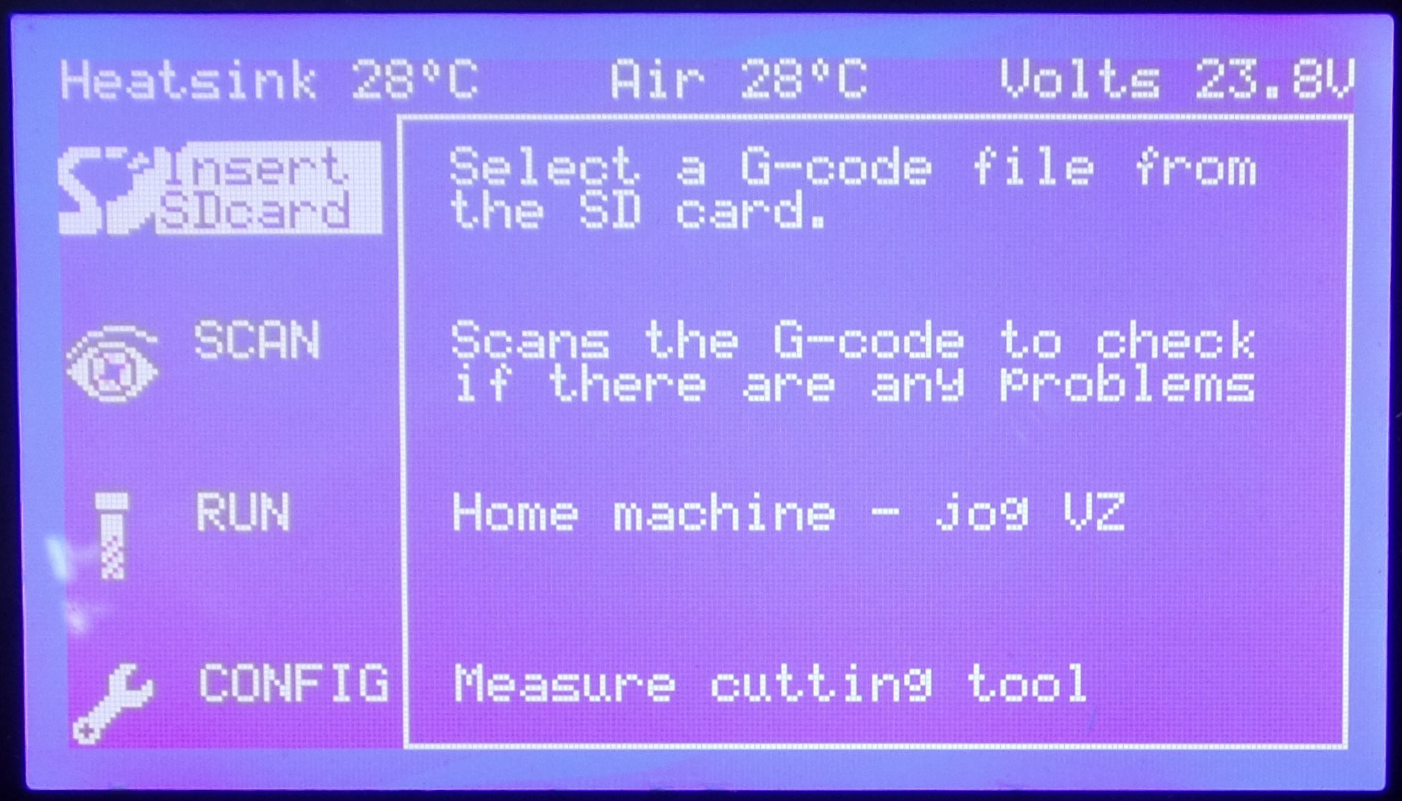
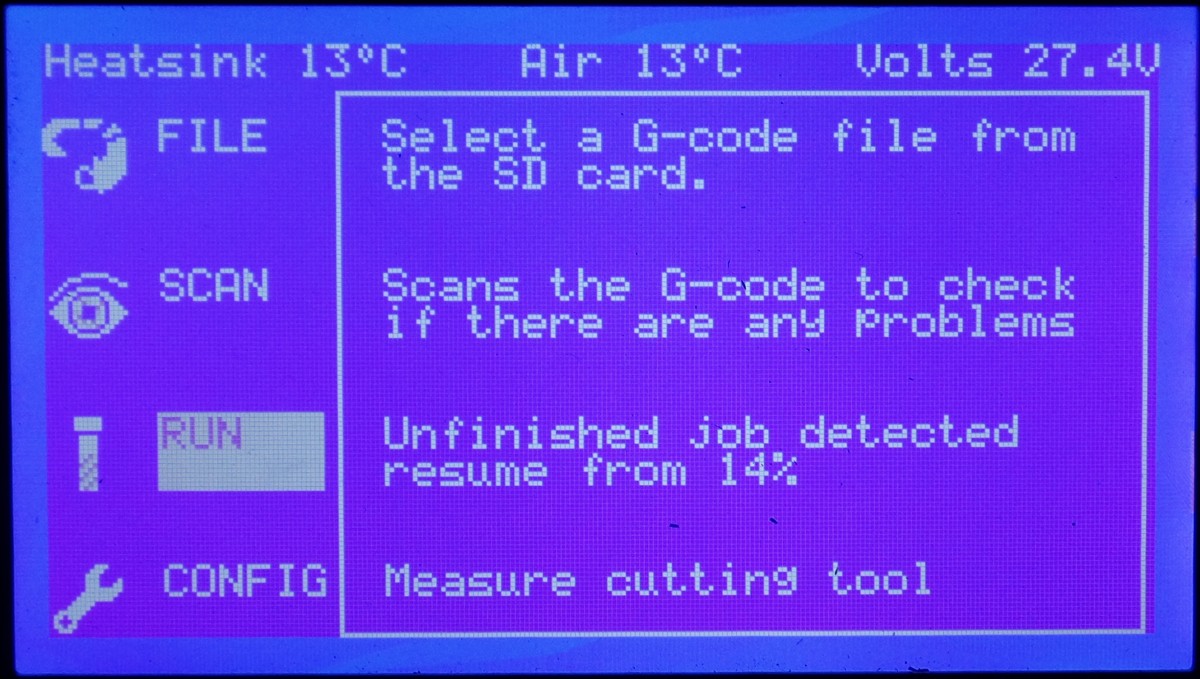
There are 4 basic steps involved with processing the g-code.
- Configure the controller.
- Select the g-code.
- Scan the g-code.
- Run the g-code.
Configuration must be performed at least once to give the controller basic information about the machine connected to it such as the size, resolution and offset for each axes. The first 3 axes are always X, Y and Z however the 4th and 5th axes can be named A, B, C, V or W to suit your g-code or disabled if not used. The time and date settings can also be adjusted.
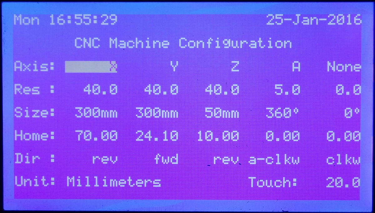
There are some additional options for changing tools and measuring the tool length. Normally a touch sensor is used to measure the tool length however there is a second option if you don't have the touch sensor. The tool is driven into the bed at low power causing the motor to stall. When the tool is raised back to home position, the steps are counted to measure the tool length.
If a Bluetooth, Xbee or WiFly module is installed then it is automatically detected. A configuration screen for the wireless modules allow you to configure them as well.
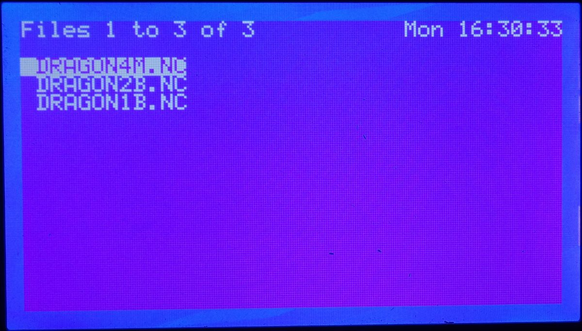
Select the G-code is pretty self explanatory however the Arduino SD library uses the older 8.3 file name format. That is the file and directory names consist of 8 alphanumeric characters and the extension is only 3 alphanumeric characters. Longer file names will be shortened. This is actually a good thing due to the low resolution of the display. It allows up to 42 file names to be displayed at once.
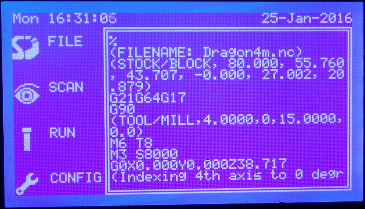
The g-code is then displayed on the screen and can be scrolled through if you need to check it.
Scan the G-code might seem a bit unusual. This is where the controller reads the g-code to determine if there are any problems such as unsupported commands which will be ignored. It also determines the size of the job and compares this with configuration data to determine if the machine can process the job. If the tool length is unknown then the controller will measure the tool length first to determine maximum clearance of the Z axis.
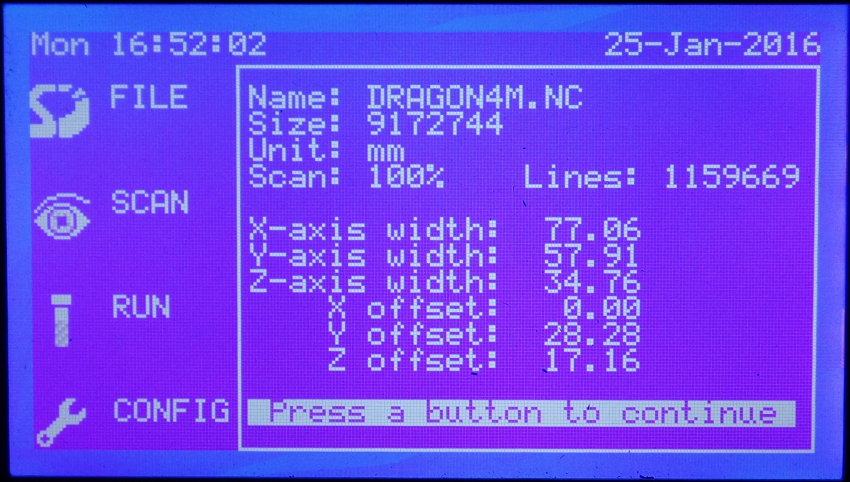
After scanning the g-code, a status screen will display basic information like the size of the file, number of lines of g-code and dimensional information about the job. Any problems will be highlighted. A 3D preview of the toolpath is then displayed. This can be useful to check the orientation of the job and the controller will let you choose to mirror image the job if necessary.
Run the G-code is also self explanatory however there are some options. To begin with, if no file has been selected then pressing run will home the machine. The navigation buttons can be used to jog the axes. This can be useful for moving the cutting tool to one side while loading the stock. It is also used to program job and tool offsets.
As a job is processed, it's current status is stored in the NV RAM of the DS1307 RTC. When the controller is restarted the previous job status is recalled allowing you to resume a job. The resume point can also be manually selected or the job can be started from the beginning.
Complex jobs might require several tool changes. When a tool change is required, the controller will move the cutting tool to a suitable position and wait for the tool to be changed. You will be required to hit the emergency stop as a safety precaution. Once the tool has been changed and the emergency stop is released, the tool length will be measured and the job will resume.