 Yann Guidon / YGDES
Having "solved" the divide-by-two question, I thought I could reuse this lesson to make a better FlipFlop for the Johnson counters. The "cascaded Johnson counters" idea was neat but... maybe too complex.
Now it's logically more consistant to have a single type of master-slave-like gate that can be reproduced all over the design. There is just one little adaptation to do: where the data comes from. In the Div2 gate, the data comes from the gate itself while for the Johnson counter, it comes from the previous gate in the ring.
The "new DFF" uses as many parts as the "augmented Latch" gate (10 transistors and 2 resistors). However it removes all the funky decoding and thus saves some more transistors.
For good measure, I added the optional asynchronous Reset for power-on reset and easy setting of the digits. It's a simpler, parallel diode system which saves one MOSFET. Beware that the diode will not pull the gate down to 0V but the BS170 starts to conduct around 1.5V so there is some margin for a slow design.
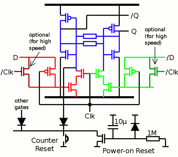
I'm pretty proud because this design uses both parasitic elements of MOSFETs for our advantage :
- the gate capacitance holds the value during the clock transition
- the body diode (of the pass P-FET) discharges the gate when the data is low
I'll test it as soon as I have a proper, working clock source...
Discussions
Become a Hackaday.io Member
Create an account to leave a comment. Already have an account? Log In.