 zaphod
the electronics on the boat are pretty simple. here's a block diagram:
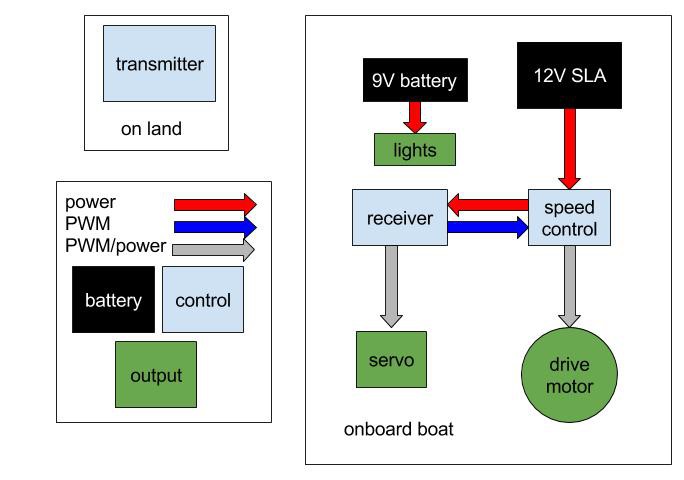
the electronics are fairly standard (and cheap) remote control electronics. as previously mentioned the transmitter receiver pair is a fairly simple 2-channel 2.4GHz setup with (supposedly) 2km of range. the servo that I am using is small enough that it can be driven directly by the receiver, so I don't need any thing more complicated to steer the boat. the servo is a simple 90 degree plastic gear servo as found in your junk box. I had originally designed my own speed control for the boat, but it ended up not working as well as I had hoped. additionally the first version of the boat's electronics had included a bilge pump but that was edited out of the design after a couple of fires. I'll be talking more about that in the next section. As of right now the speed control and receiver power are handled by a cheap ESC circuit that I found online (dx.com, don't have the exact link right now. I can dig it up if anyone's interested). the drive motor is a simple DC motor that I pulled out of a broken printer, it works shockingly well considering were it came from. the whole mess is powered by a 12V sealed lead acid 'alarm' battery. I went with an SLA for a few different reasons. firstly cost: they are dirt cheap compared to other remote control batteries. Secondly ease of use: depending on the specific chemistry of the battery rechargeables can be pretty picky about charging cycles, generally speaking lead acid batteries are not, also I already had a charger in my junk drawer. Thirdly weight: SLAs weigh a ton, which is not an advantage if you're trying to build a quadcopter but is great if you have to displace a few litres of water to get the correct draft.
the boat also has some navigation lights, specifically the port, starboard, and aft lights, although no masthead light because I'm lazy. since I don't have enough channels to control the lights from my transmitter I just plug them in when I want them on and leave them unplugged when there are unneeded. the lights are just coloured LEDs running of a 9V.
main electronics:
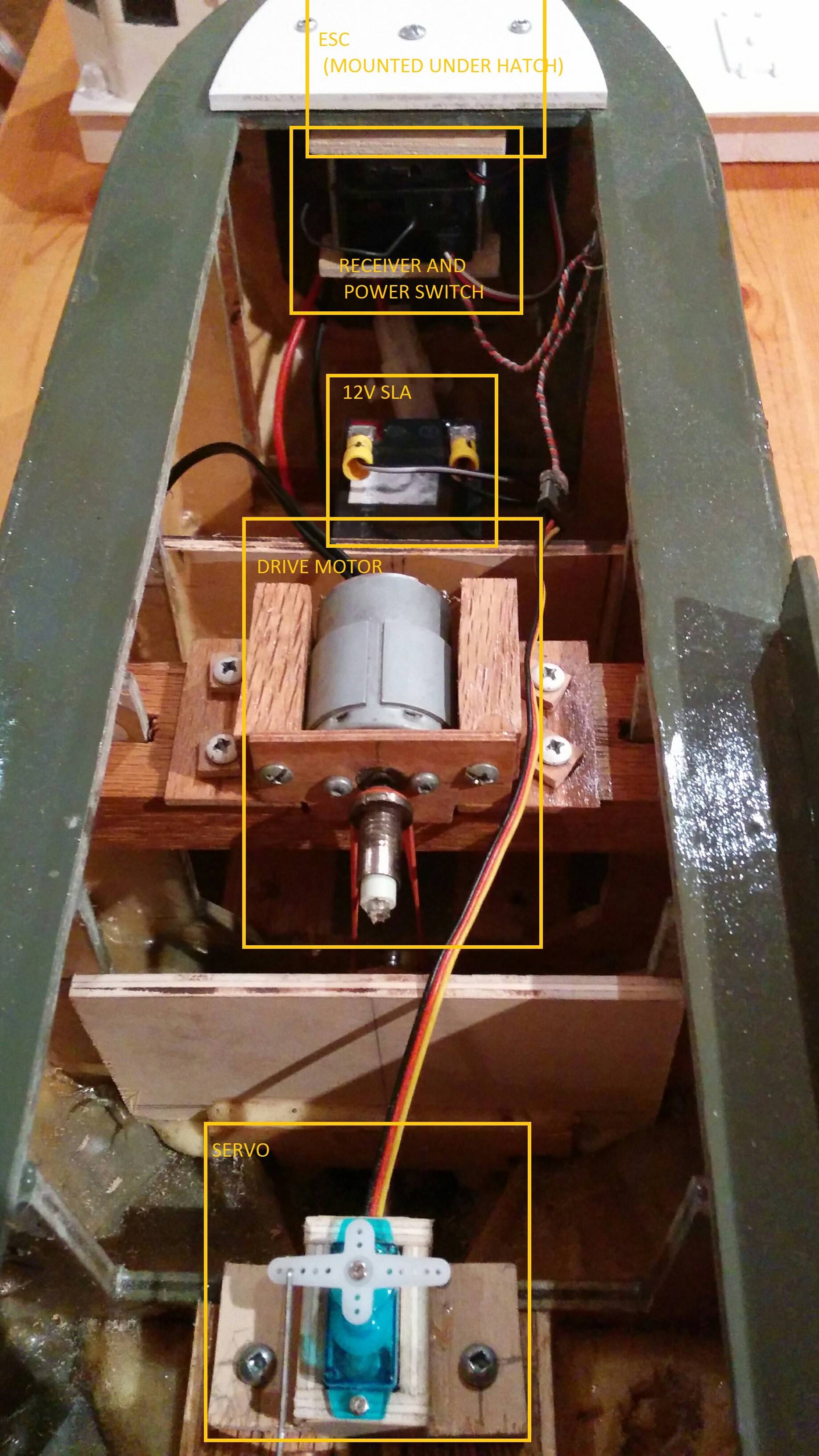
this picture is taken from the aft looking forward. note the belt drive on the motor.
and here it is with the lights on:
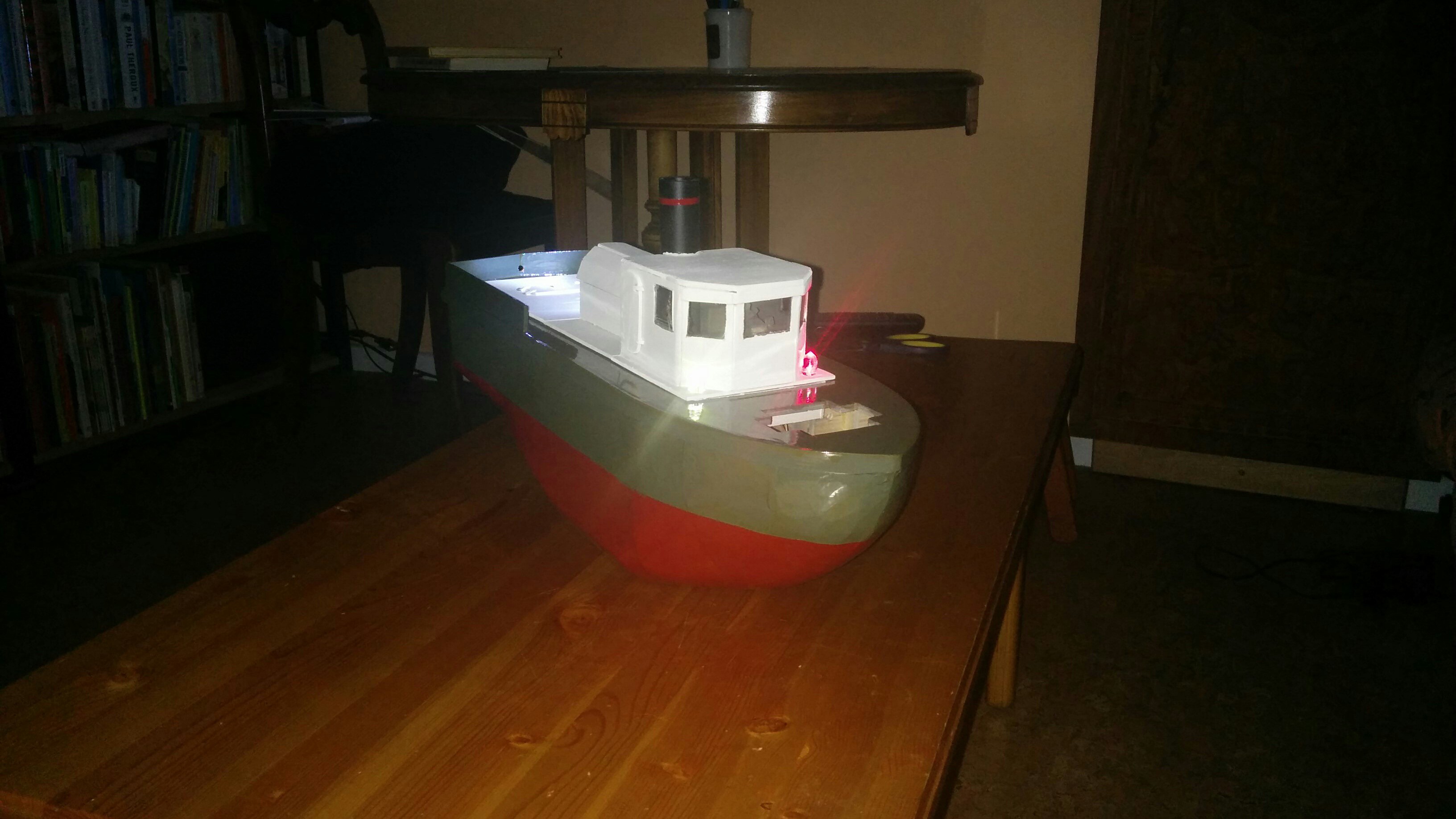
no point in including pictures of the wiring behind the lights, its pretty much just a resitor soldered to an LED.
Discussions
Become a Hackaday.io Member
Create an account to leave a comment. Already have an account? Log In.