 Benchoff
This is it. I have verified hardware, and somewhat working firmware. Everything is ready to move into production. I'm going to be spending thousands of dollars at Mouser very very soon, and thousands more are going to a board house in China. MrRobotBadge Mk 2 is happening, whether I like it or not.
My initial plans for this badge were quite grandiose. I would have more LEDs, more blinky, and -- because I could -- an injection molded plastic enclosure. Yes, I wanted to do an injection molded plastic enclosure for this year's MrRobotBadge. This meant getting molds made, injecting hot plastic, contracting things, and spending tens of thousands of dollars for an indie Defcon badge. This plan fell apart when I attended Shmoocon in January. Someone had beaten me to the first injection molded conference badge.
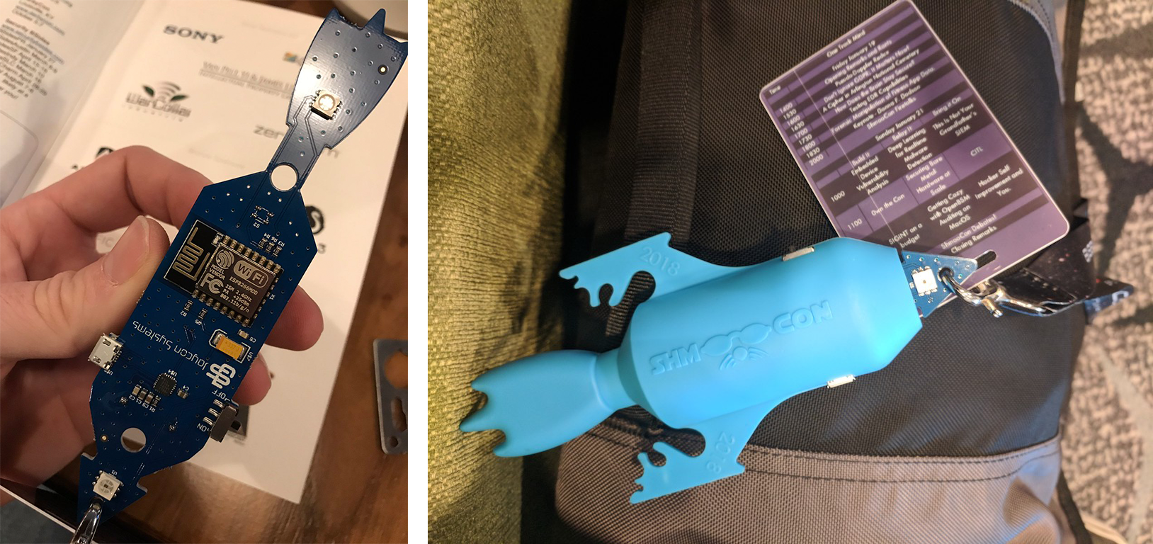
The Shmoocon badge this year was basically an ESP8266, a few serially addressable LEDs, and an extraordinarily fancy injection molded rocket enclosure. All of this was done by Jaycon Systems, which to me feels like cheating, but if you want the latest in badgelife, there you go. Go with Jaycon. They were the first badge that I'm aware of that did injection molding.
Injection molding was right out, but around the same time as Shmoocon, I came across an interesting LED driver. The ISSI IS31FL3741 is a LED driver that takes I2C in, and spits out a 39x9 LED matrix. It's the same family of chips as the IS31FL3731, the chip I used on last year's MrRobotBadge, but the new chip is significantly more blinky. If you do the routing right on the PCB, you can do an 18x18 LED matrix.
There's one problem with this chip: it was scheduled to ship in Q2 of 2018. That's early April or so. Not a problem. This gives me about four months to come up with a design, do some art, and procrastinate until the chip ships.
And that's exactly what I do. I sit on my ass for two or three months. Around the end of March, I start the design in earnest. I come up with this:
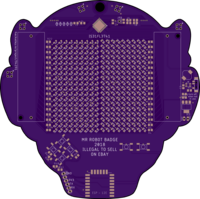
Basically, it's a rehash of last year's badge, only with more LEDs. There are a few changes:
- Instead of the Microchip MCP1640 switching regulator, I'm using the Skyworks AAT1217 switching regulator. A lot of the badgelife crew have used this regulator, and compared to the Microchip one, it's about the same price. It also sucks batteries dry.
- Instead of four AA batteries like last year, I'm only going with two. The design of the badge doesn't allow me to place batteries on the back, so everything here is a single-sided design. This cuts down on the area I can place components, and ultimately how large the display can be. I've learned a few things, though: I'm using keyed battery holders. Last year, I had a few misplaced battery holders that were soldered in the wrong polarity. The Keystone 1028 has a neat little plastic nub on the bottom of the positive terminal of the holder. If you put a hole in your board, this means the battery holder can only be placed in one way. That's going to be great for when I recruit friends and family to help with the assembly
- Changed around the pin mapping of the buttons. I really fucked that up last year.
- Added five shitty add-on connectors. The Shitty Add-On standard is going on a ton of indie badges this year. It's just power, ground and I2C. Enough to have fun with, at least.
- The software will be infinitely better.
With the design in place, I sent that board off to OSH Park, hit up ISSI, asked for a sample of chips, and they actually got back to me. They immediately sent me the dev board for this chip, but no chips. I needed the chips to prototype this board. I needed them to assemble this board. Without samples of chips, I couldn't do anything.
I checked Mouser every day for a month. At one point, Mouser was getting one reel -- just 2500 chips -- on May 28th. While I was waiting for these chips, I started to get a little nervous. I actually made a 'safety' version of this badge using three of the LED drivers I'd used from last year. This was a four layer board which would have pushed my costs up dramatically, and buying two extra chips at $2/piece would have pushed the BOM cost right to the limit. Still, I needed a fallback plan.
On April 20th, the samples of chips from ISSI arrived. A few days later, the chips were available on Mouser. Everything was good. I got my stencil out, and started placing LEDs. Throw everything in a toaster oven, and we'll see how things turn out.
But I'm an idiot. I had planned on using the Skyworks regulator to get a 5V rail in the circuit, because that's what the new LED driver needs. For the ESP, I needed 3.3. That means a linear regulator, in this case an LM1117. I ordered a handful of LM1117s. It was right after I soldered the board that I realized the LM1117 is an adjustable output linear regulator. I should have bought the LM1117-3.3. No problem; I used one of those on last year's prototypes. I'll just steal one from that.
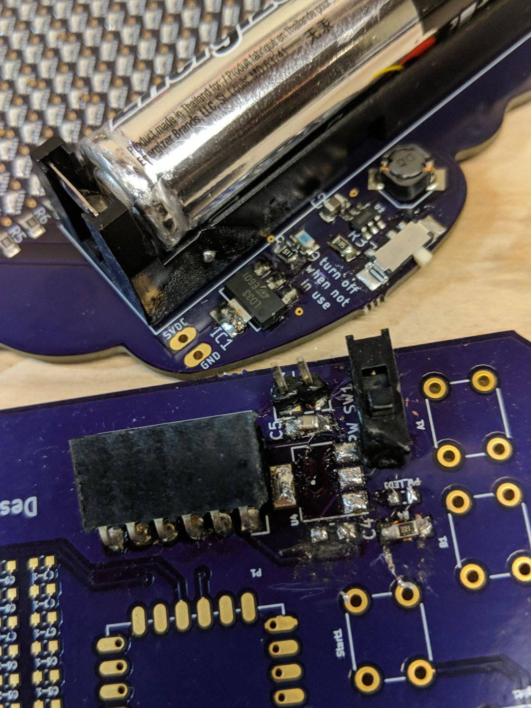
With the LED driver chip getting 5V, and the ESP getting 3.3V, it was time for the next step in bringing up the badge. I had to flash some firmware. But there was a problem on the 3.3V rail. It was shorted, somehow.
Here's where I'm a god damned moron.
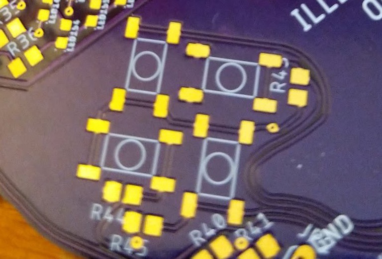
See that? Those are the pads for the buttons. Buttons, as you should be aware, have four pads. Each side of those pads are connected together electrically, Oh, but which side, you may ask? The long sides are always connected; it's the short side that are switched:
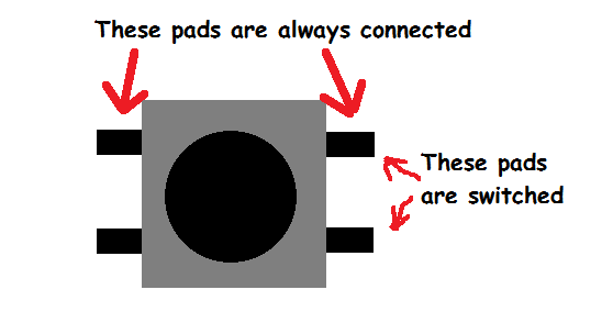
So I'm an idiot, but that's nothing some kynar can't take care of:
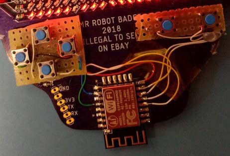
With that, I got the badge working. I could upload code, and the LEDs sorta worked. I had forgotten how hard it was to solder QFNs. I got some of the LEDs working, but to verify everything, I needed a completly working badge. I can't do that by hand. I needed a pick and place machine. I turned to Macrofab. For about $100, I could get a single badge made. Thankfully, by this point, the LED drivers I needed were in stock. In ten business days, I had a prototype:
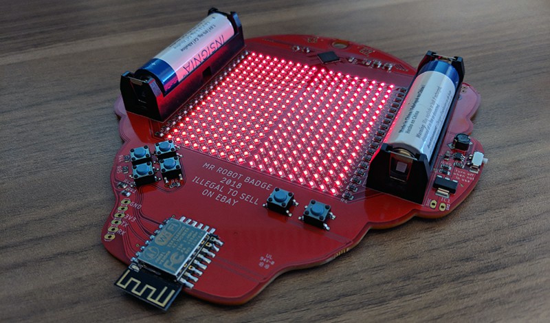
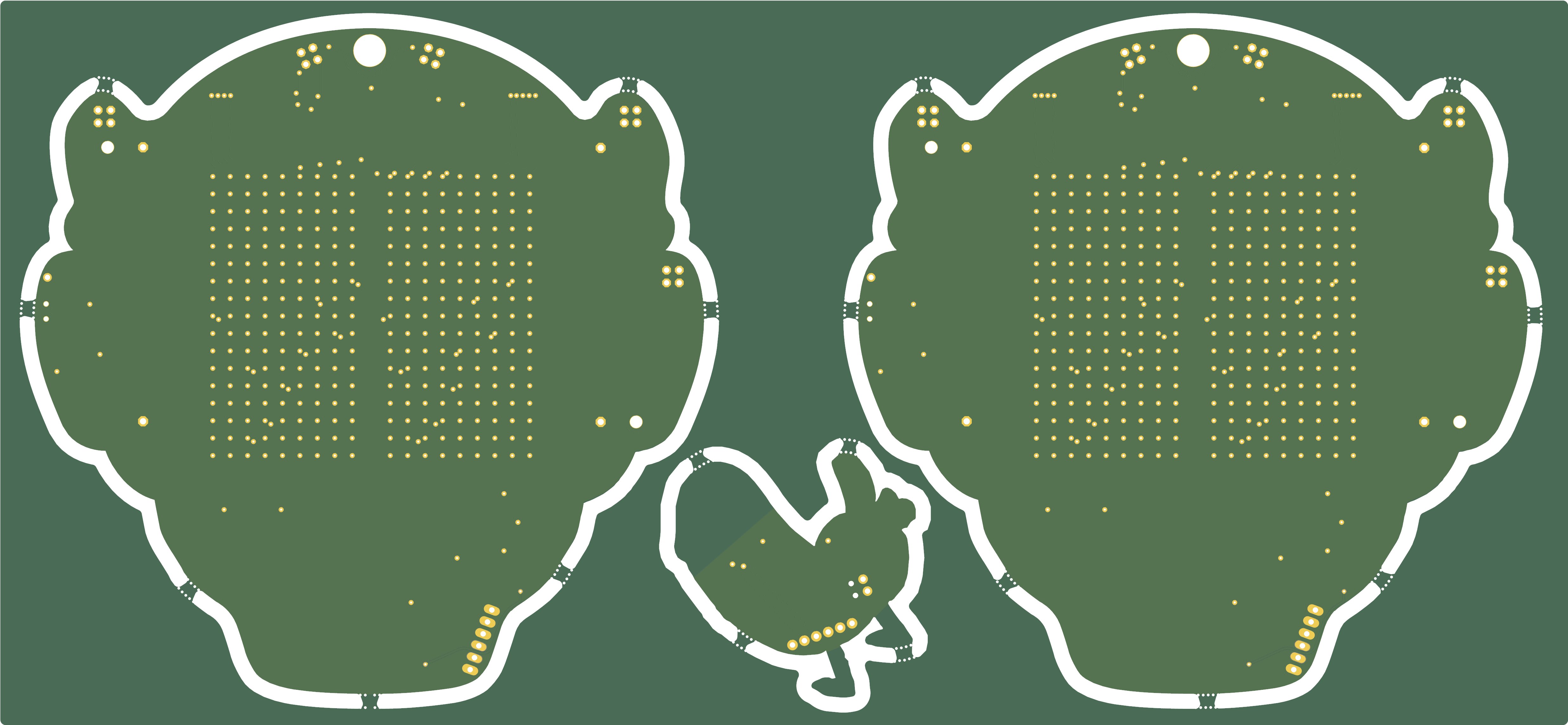
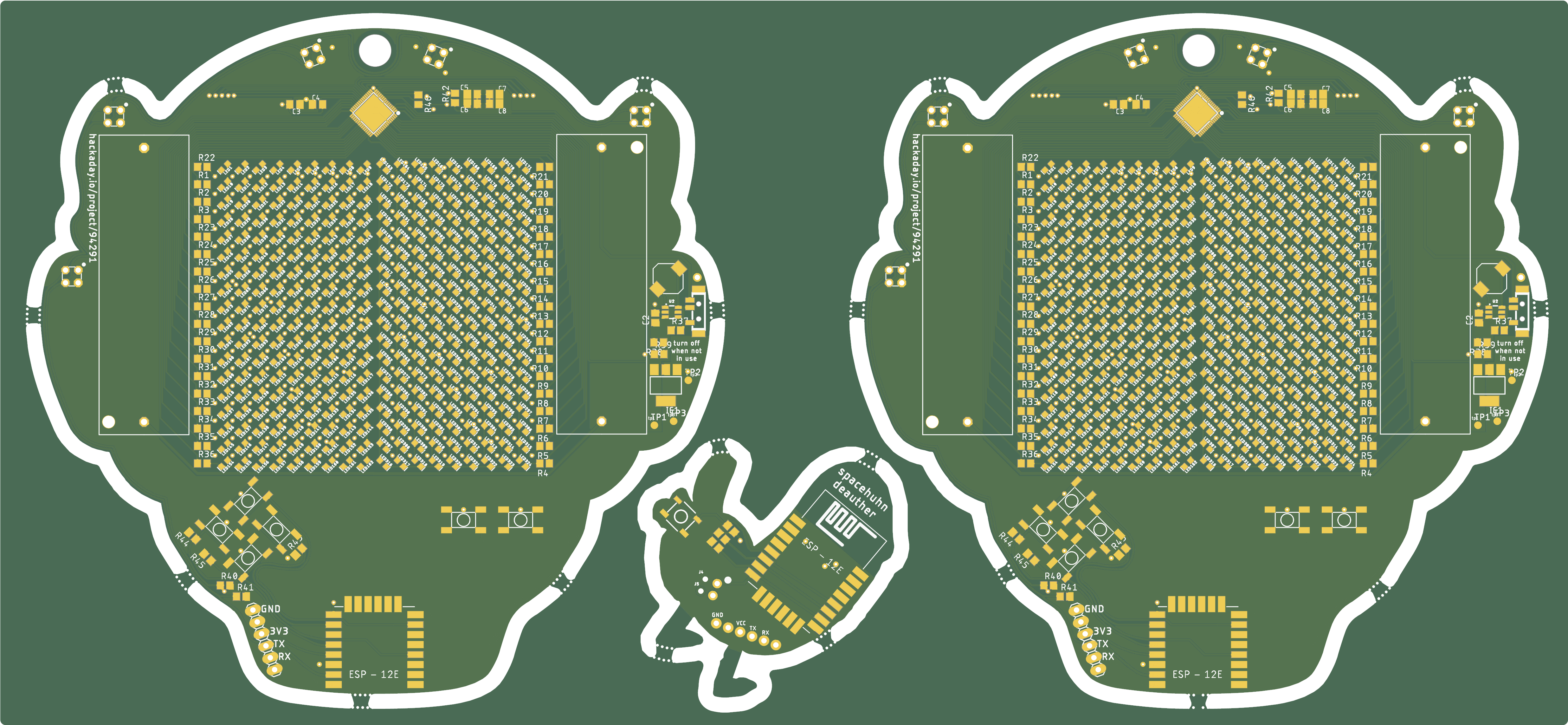
That's it. That's the prototype, and how I got to one MrRobotBadge. From here, I have a few things to do. I need to make a panel to send off to the board house. For this, I used the GerberPanelizer from
ThisIsNotRocketScience. I also included a shitty add-on in the middle of the panel, just to make things fun. You don't see the art on this board, and it's green, but trust me, it's there in the gerbers.
Now, a word about costs. Like last year, I've been keeping track of my expenses. To get to this point, I have spent $4841.77. That's four thousand, eight hundred forty one dollars and seventy seven cents. I have exactly two prototypes.
This does include some of the parts that are going to go into production. It includes $350 in anti-static bags. It includes two thousand dollars in LEDs. It includes a four hundred dollar Mouser order (most of my passives for the entire run -- the cheap shit), and it includes a thousand in battery holders. However, I still have thousands more to spend to turn one prototype into thousands. This is not an inexpensive endeavor.
But this is going to happen. I'm going to have a ton of badges at Defcon. All I need to do is make a thousand more.
Discussions
Become a Hackaday.io Member
Create an account to leave a comment. Already have an account? Log In.
I love those ISSI chips, and the people there were super-friendly when I asked for samples (though they also had some problems getting the packages I asked for, but in the end they delivered them). Even if those chips are a bit on the expensive side, I love the integrated solution and not having to have separate source and sink chips and having to do multiplexing in software.
Are you sure? yes | no
I think there is a physical law that you have at least one bug in the first revision of a PCB. Even for simple PCBs I can't do it right the first time :-)
But why did you buy all the parts? When I ordered my Kerberos and Bloxorz cartridge PCBs, the assembling company ordered the parts for me.
Interestingly an additional batch of Kerberos PCBs from pcbcart.com in China was not much less expensive than ordering it from a local German manufacturer, hupperz.de. But it was only a batch of 50, might be cheaper for hundreds. But the board is expensive, with special hard gold plated fingers for the cartridge contacts and a beveled edge. Which company do you use for soldering the parts and how much does it cost?
Regarding the chips: I never design any (commercial) circuit where the parts are not in stock at Digikey or Mouser. Especially if you have a hard deadline, it is too dangerous to use new components. And usually ICs have bugs as well. Better wait till they have sold a few, customers complained, and they created a new revision where it is fixed (errata sheets of complex microcontrollers can be fun. I2C? no, it doesn't work at all, no workaround known).
Are you sure? yes | no