 ottoragam
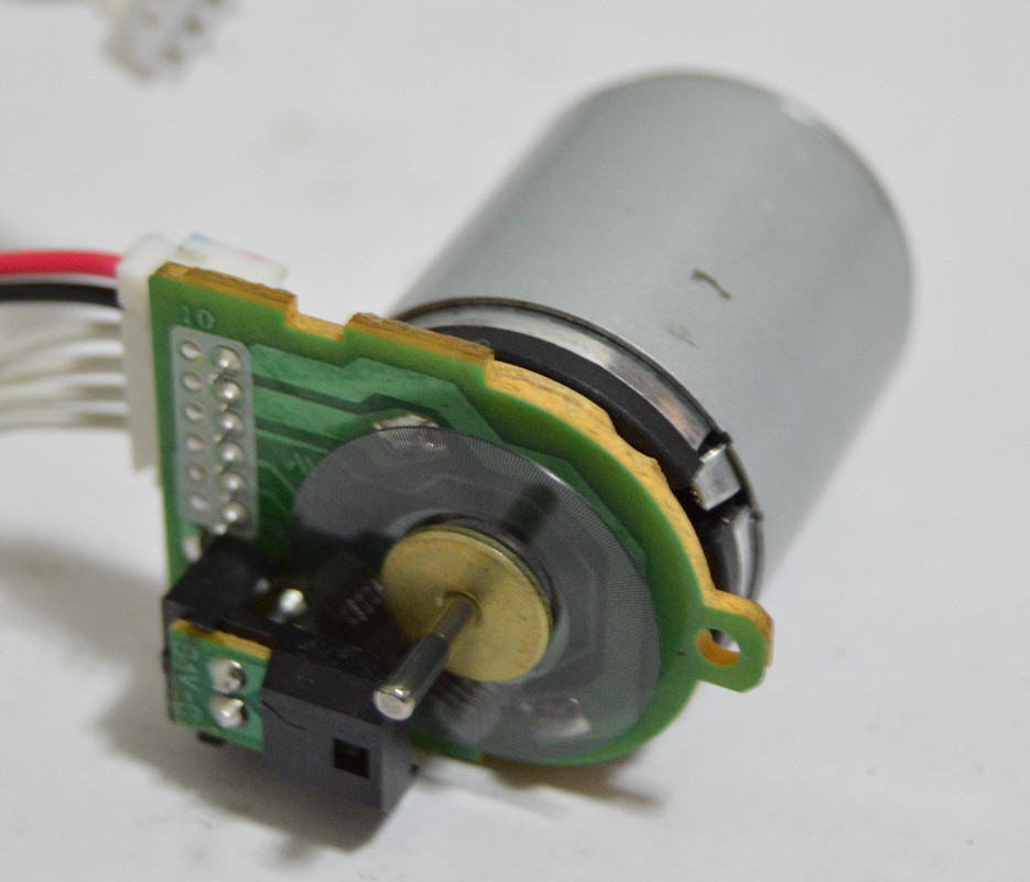
I wanted to find if the controller could accept a higher STEP pulse frequency, so I took out a Mitsumi printer motor with an integrated encoder (334 divisions, 1336 cpr with 4x decoding) from my parts bin.
One could argue that the MCU may be missing more than one step pulse, thus not meeting the error condition, but I find very unlikely that the microcontroller misses the "correct" amount of puses tens of thousandths of times during the short test.
The video shows me measuring the signal frequency on one of the encoder channels, and then measuring the STEP input frequency, wich is nearly 4 times higher as is supposed to be.
You can see the error LED turning on at the end of the video when I disconnect the encoder, causing the drive to detect an erroneous quadrature sequence.
Discussions
Become a Hackaday.io Member
Create an account to leave a comment. Already have an account? Log In.