The idea for the bytebox came shortly after discovering the blinkstick. After scrambling for ideas to justify the purchase I decided on something simple. Making it temperature controlled, displaying colour to represent the current room temperature.
Having some experience in software but none in GPIO programming with the Raspberry Pi I decided to start with a basic prototype.

This was programmed initially to display blue for temperatures below 22 degrees Celsius and red when the temperature reached a toasty 22 degrees Celsius and above.
Whilst waiting for the delivery of the blinkstick I was itching to add more functionality and a more accurate way of seeing the temperature outside of the blue and red leds.
I started looking into the internet of things for real time viewing of data from mobile devices.
After a little trial and error I managed to get my basic prototype online and sending data to Thingspeak.

The blink stick arrived and was super easy to setup and a few commands later I was sending colours to the blinkstick via SSH to the Pi.
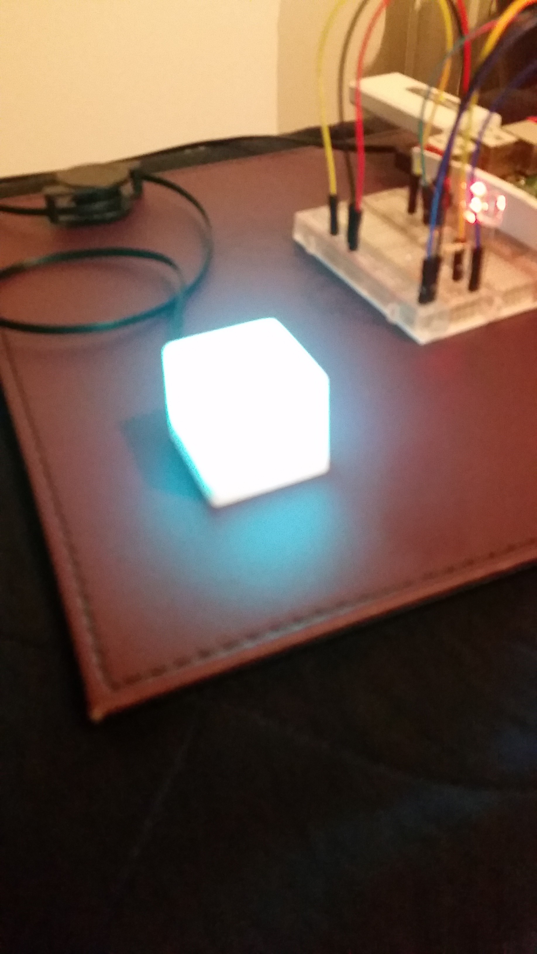
A few lines of code added to the main script and it was all setup to move on from the Red/Blue LEDs on the breadboard to the blink stick. Initially it was setup for 3 temperatures to show Cold (Blue), Optimal (Green) and Warm (Red).
After a little while of tweaking the code and adjusting the ranges slightly one thing that I decided I wanted was dynamic colour shifting based on temperatre as the dramatic shift between the 3 colours would be sudden and distracting.
At first I expanded from 3 to 8 colours and used the blinkstick APIs Morph function which gently shifts from its current colour to the next defined colour. This worked fine and gave a colour changing effect which was less sudden.
However even with this I felt only having 8 colours for a range between 10 and 30 degrees Celsius wasnt an accurate colour representation so I needed to go back to the drawing board and rethink the way colour changes.
After a while of cycling through various different options I settled on using an image file with a custom gradient going from Blue to Red through Cyan, Green, Yellow and Orange.

Each pixel on the horizontal line represents a temperature starting at the left side (blue) which is 10°C and moves through to the right in 0.1°C increments. The function for handling this takes a temperature value and matches this to its index number which is directly linked to the pixel value on the H axis. The pix function of the PIL library then fetches the RGB value of the pixel and returns this. The RGB value is then sent to the Blinkstick and is displayed on the coloured cube.
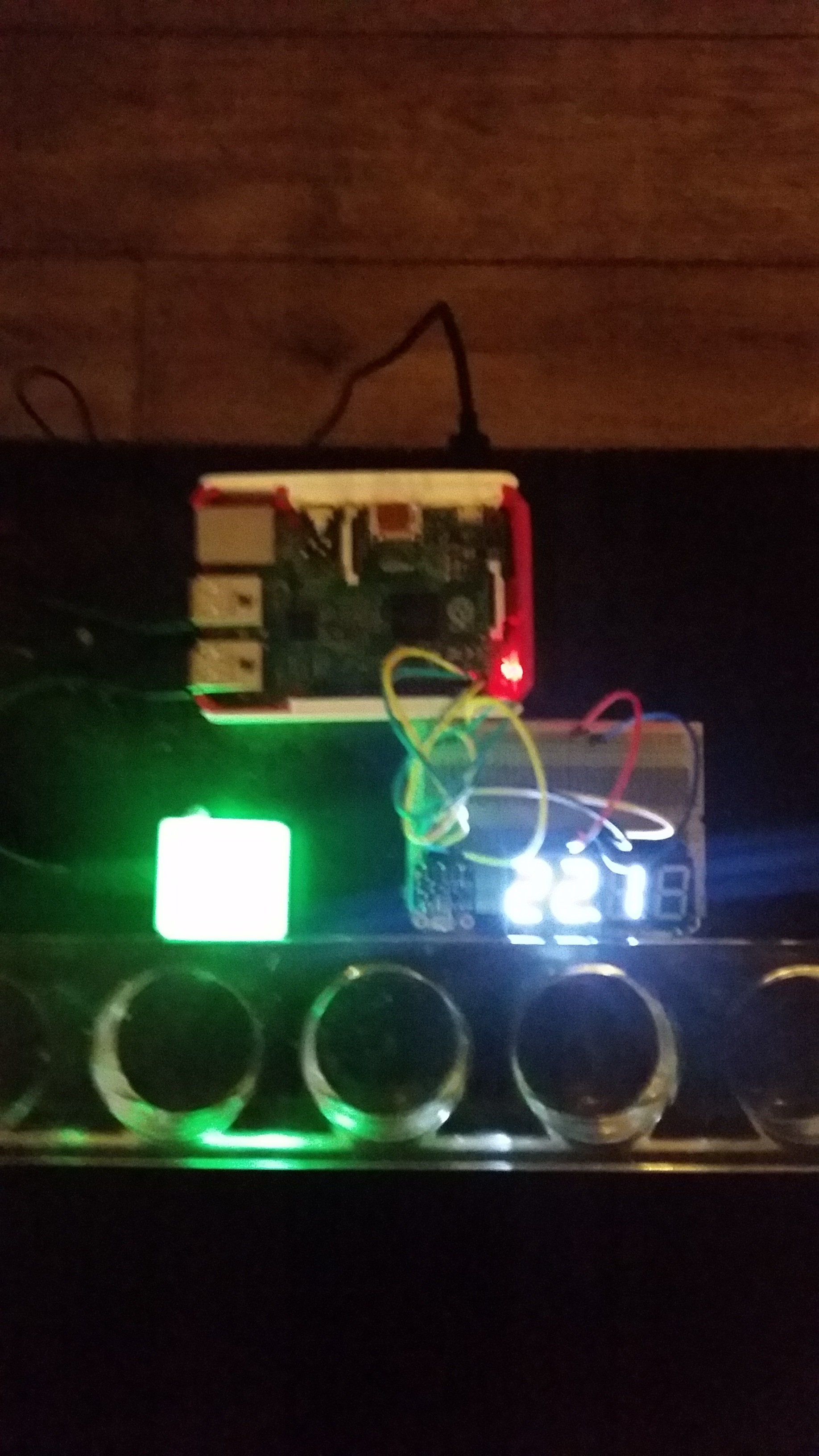
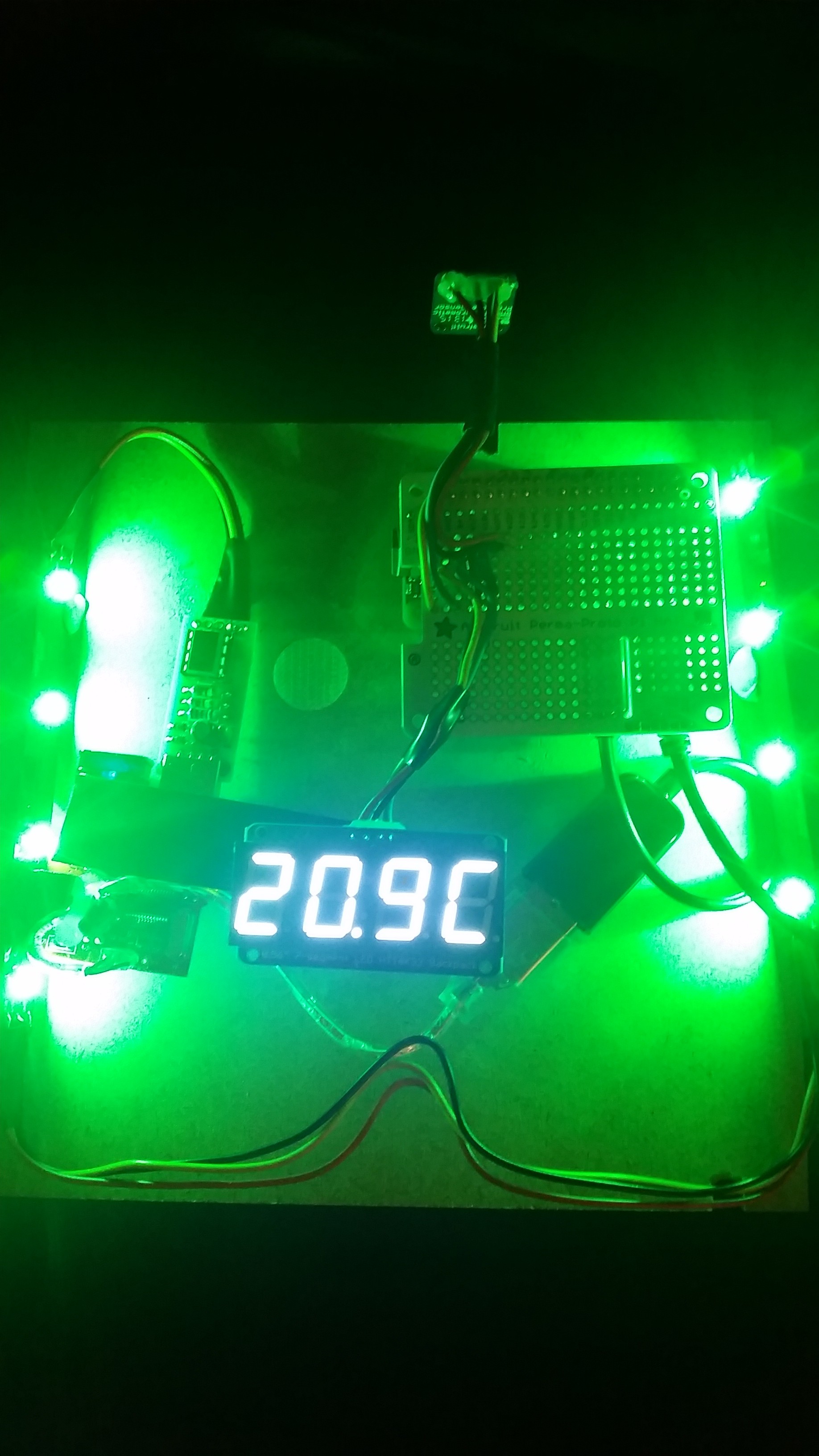
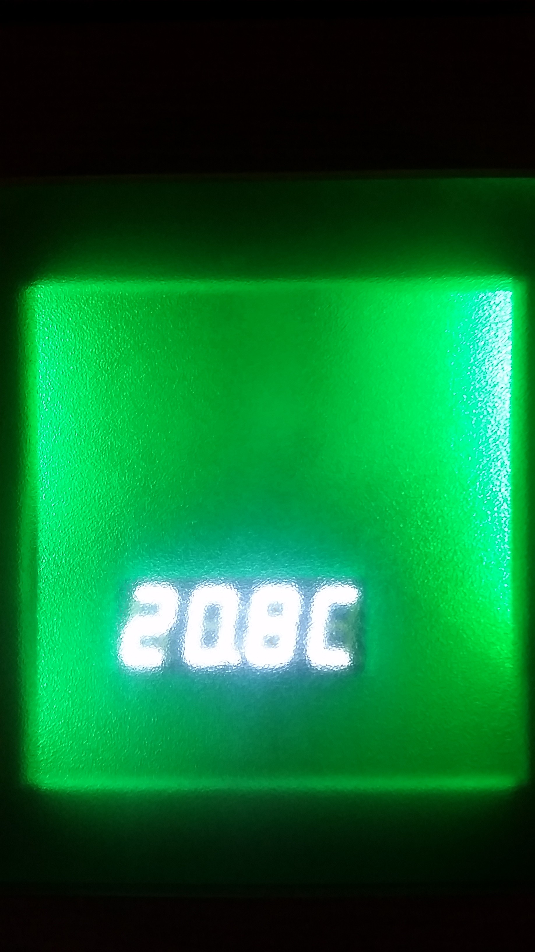
The idea to include a 7 Segment display came fairly late on into the project but I had always wanted to use one so I decided to include it and use it to display the exact room temperature (Even with a tonne of new colours displayed it was still nice to see the exact temp!)
The idea for this would be eventually to mount it to the front of the housing and have it be visible through a defused glass or plastic section.
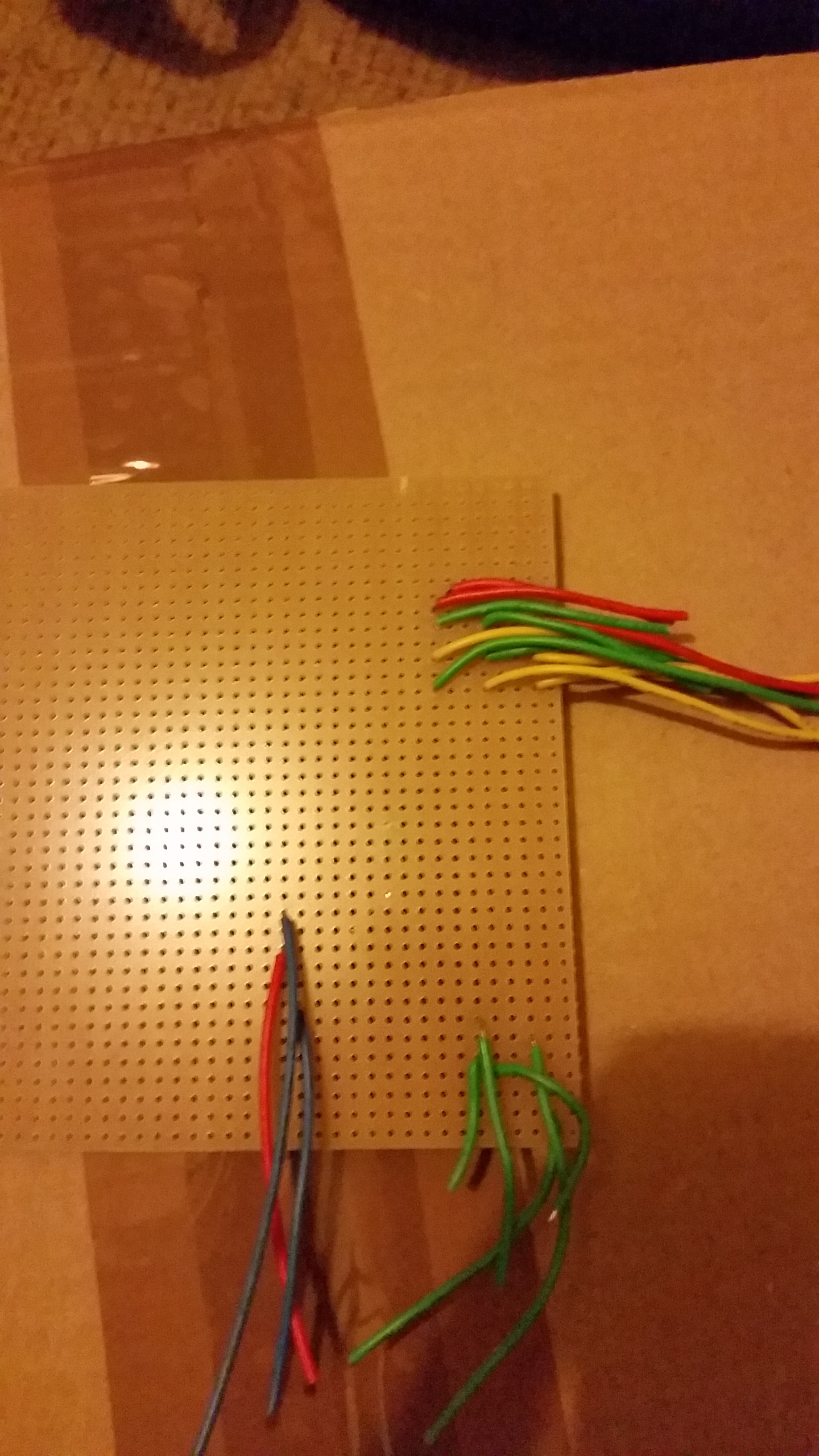
Once all the code was written and the hardware prototyped and fully tested it came time to solder it all together. This would be the first time soldering and knowing I would need to solder the 40 pin header to the Pi Zero ( even more daunting knowing how hard they were to get a hold of, and still are!). I started out soldering some odd bits of wire to a copper PCB I picked up at Maplins.
After a little while I tired of the practice soldering and wanted to jump into the real thing so I soldered the pins to the BMP180 temperature sensor and the 7 Segment Display and all was disaster free!
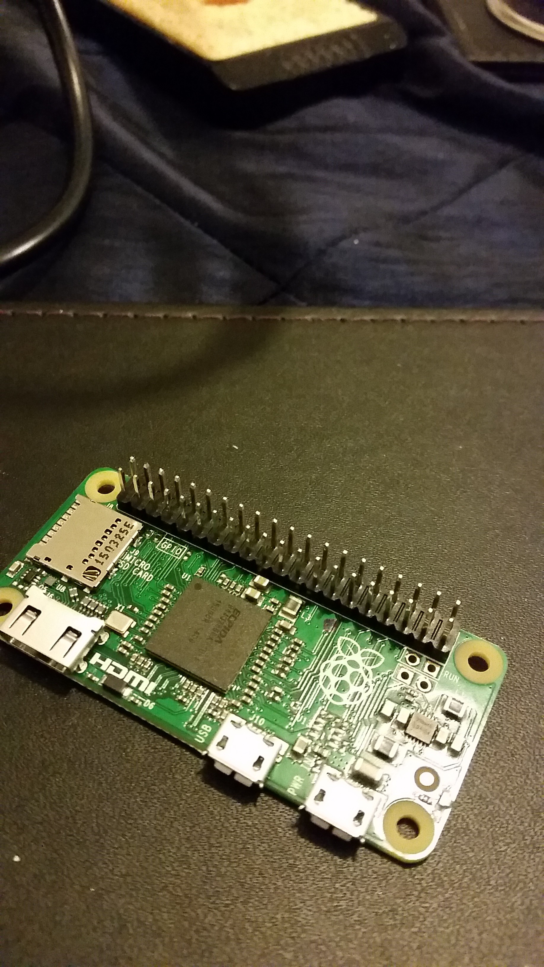
Next I soldered the 40 pin HAT header and the 40 pin Pi Zero header. I started with the HAT to get used to soldering the close pins and build confidence ready for the Zero.
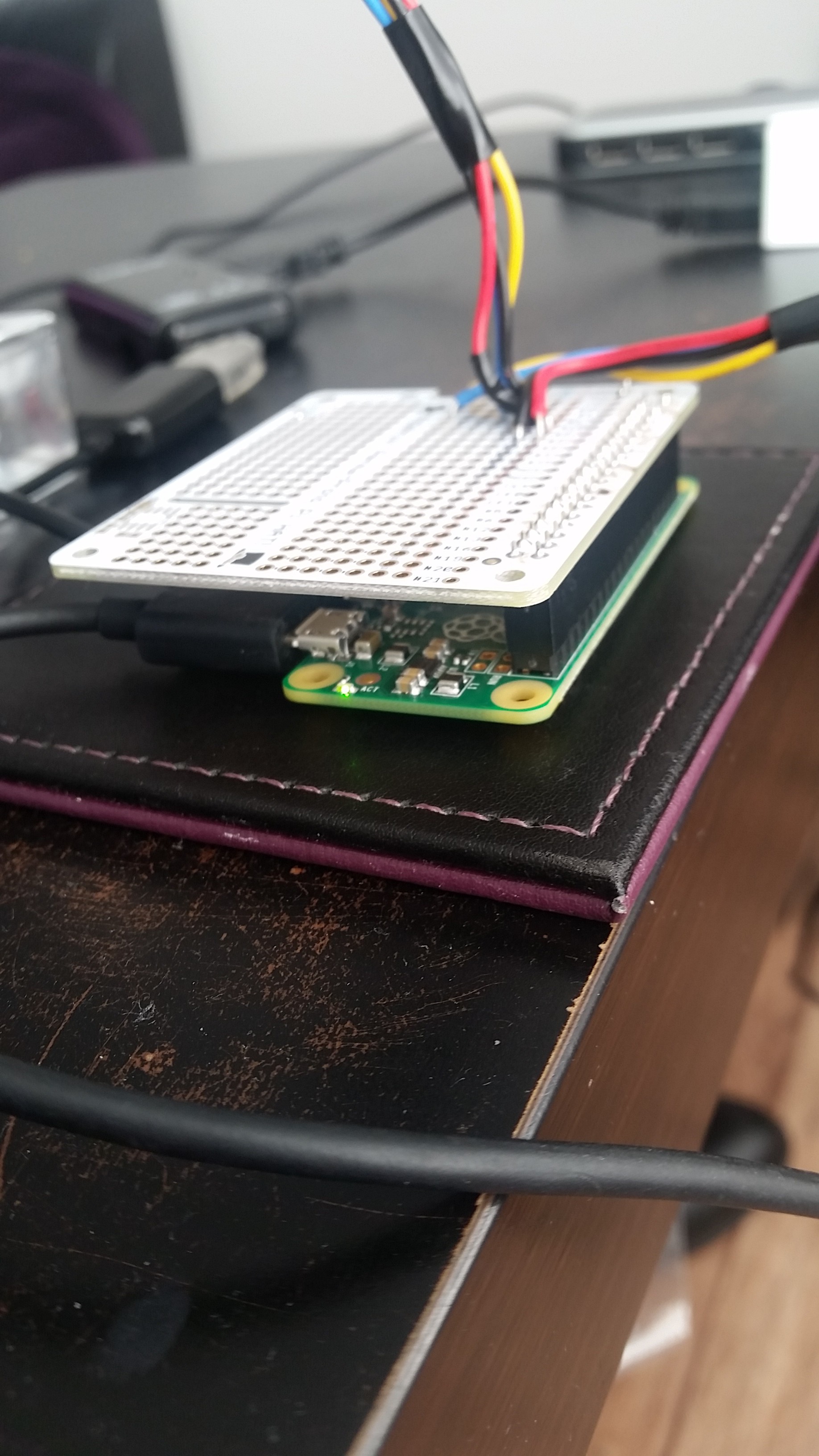
Pi Zero + Header:
Pi Zero and its nice new HAT:
Next stage was finding a suitable housing for the project, initially I had planned to fit it all into a perspex cube. I had checked out the various options for this including making my own and having one 3D printed. But both options turned out to be fairly expensive. Eventually I decided to house the project in a box frame with a frosted glass front.
This was completed however I don't have any images as it didn't stay assembled for long. I wasnt happy with the final outcome. The Blinkstick square I was using was mounted too close to the glass panel and the light from this wasn't properly defused and only illuminated a small section. To combat this I decided to rethink the lighting and look for a deeper box frame.
The solution for the lighting was to opt for the Blinkstick Pro and use 2 strips of LEDs mounted on the side of the casing behind the glass. This was the outcome:
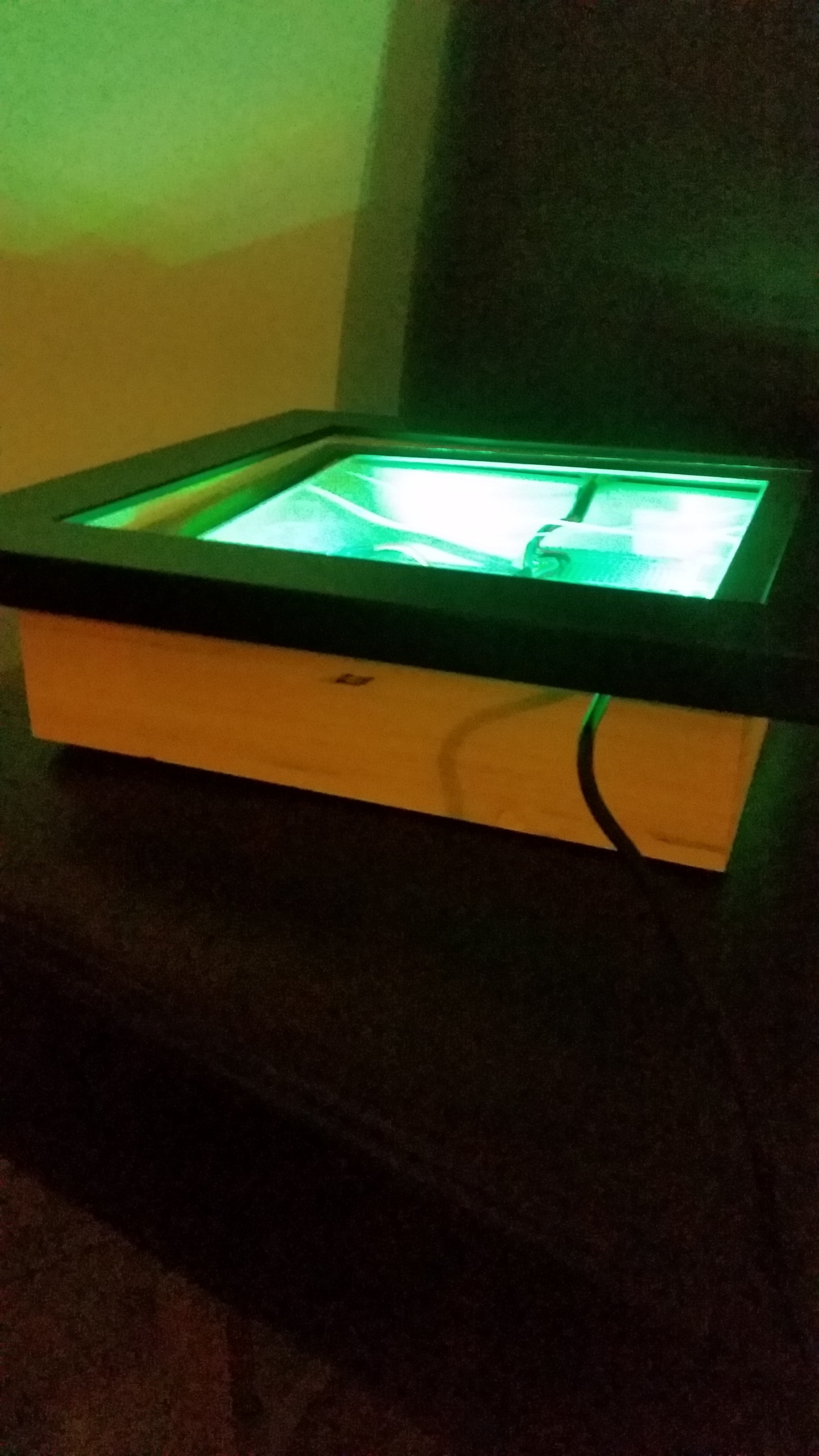
And the frosted glass frame on top:
Sorry for the blurry image but as you can see from this it gave a much more even distribution of light. At this stage I was happy with the light arrangement but the frame still wasn't perfect, it was only 22mm deep and whilst this was enough to fit everything in, it was a little too snug for my liking.
I found this 40mm deep box frame on Ebay for a reasonable price:
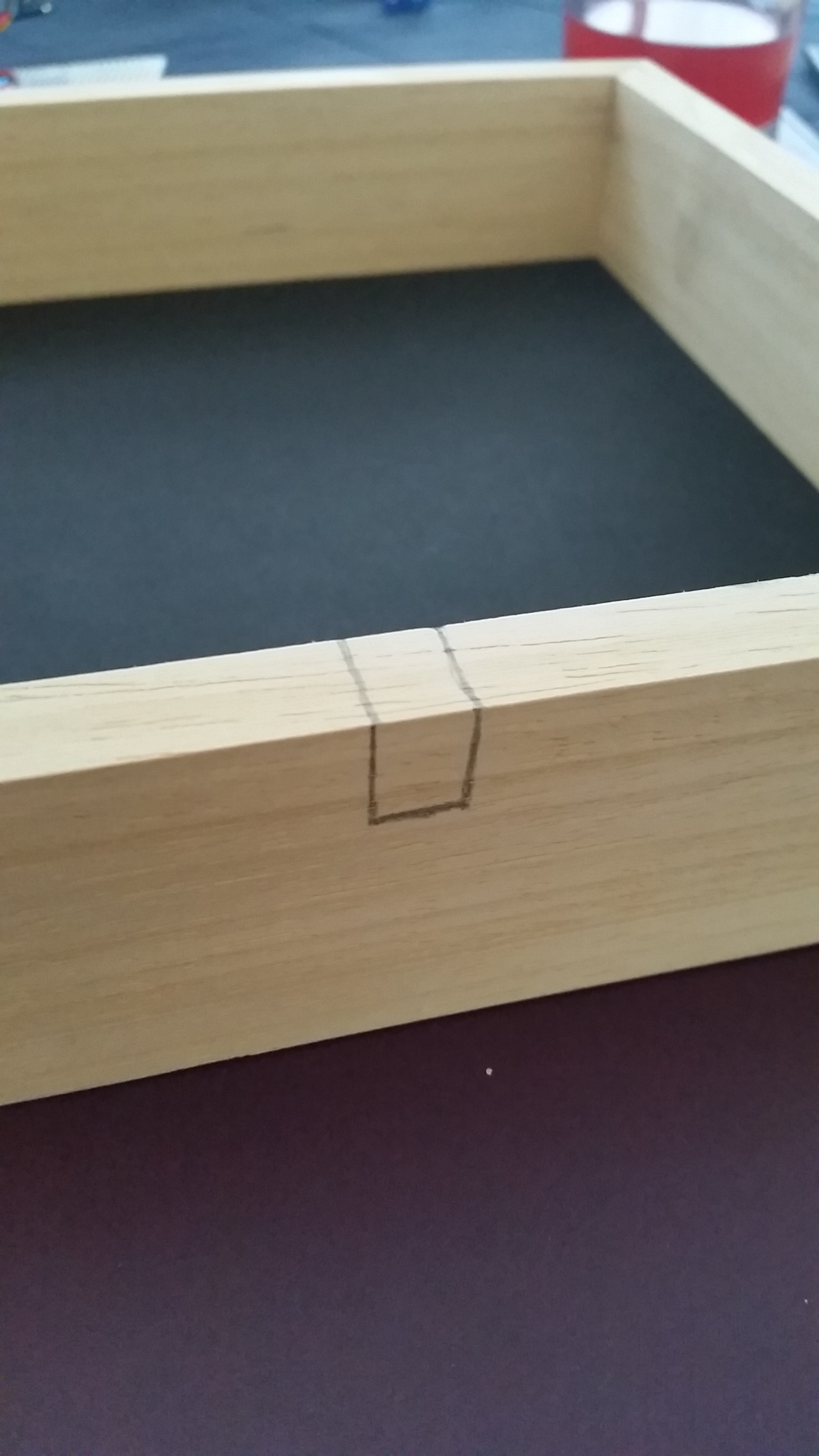
Everything about this is a much better fit, just needs a few bits cutting out for the temperature sensor and the power cable to go out the back:
I will update once this has been completed and the project should then be completed. Fingers crossed! :)
Discussions
Become a Hackaday.io Member
Create an account to leave a comment. Already have an account? Log In.