 Russell Kramer
I went back to the drawing board and designed a new 1024*768-60Hz VGA signal generator based on a crystal oscillator.
Here's the first design I came up with
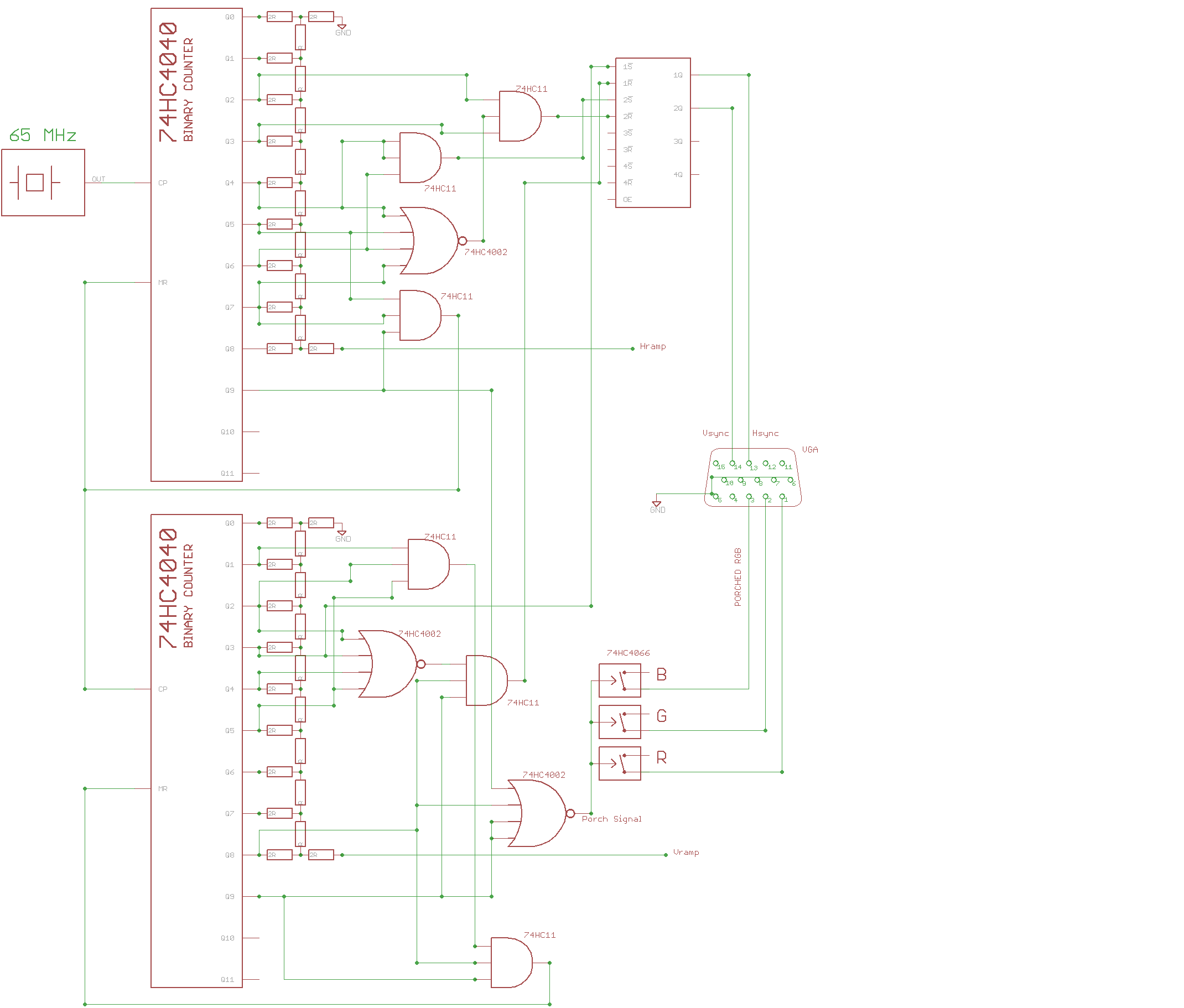
In this design the ramp signals are generated with an R2R ladder DAC instead of triggering a capacitor to charge from a regulated current source.
There are two 74HC4040 Binary counters, one for horizontal timing and one for vertical timing. The horizontal 74HC4040 is clocked by a 65MHz crystal oscillator.
- After 1,024 crystal oscillations horizontal porching begins.
- After 1,048 crystal oscillations the Hsync pulse begins
- After 1,184 crystal oscillations the Hsync pulse ends.
- After 1,344 crystal oscillations the horizontal porching ends and the loop resets. (drawing the next scanline)
The vertical 74HC4040 is clocked by the end of a scanline.
- After 768 scanlines the vertical porching begins
- After 771 scanlines the Vsync pulse begins
- After 777 scanlines the Vsync pulse ends
- After 806 scanlines the loop resets (drawing the next frame)
I implemented the timing logic by running the binary counter outputs through two 74HC4002 (dual 4-input NOR gates), two 74HC11 (triple 3-input AND gates), and one 74HC4044 (Quad SR latch). The SR-latch makes logic like "keep the Vsync pulse active from 771 to 777 scanlines" a lot simpler. A karnaugh map of that logic results in half a dozen AND and OR gates. With an SR latch I only need some logic to create a pulse to turn on the latch at 771 and another pulse to turn off the latch at 777.
This is the PCB for the circuit. Only the bottom two-thirds are part of the VGA signal generation. The upper section is sample-and-hold circuitry that I'll cover later.
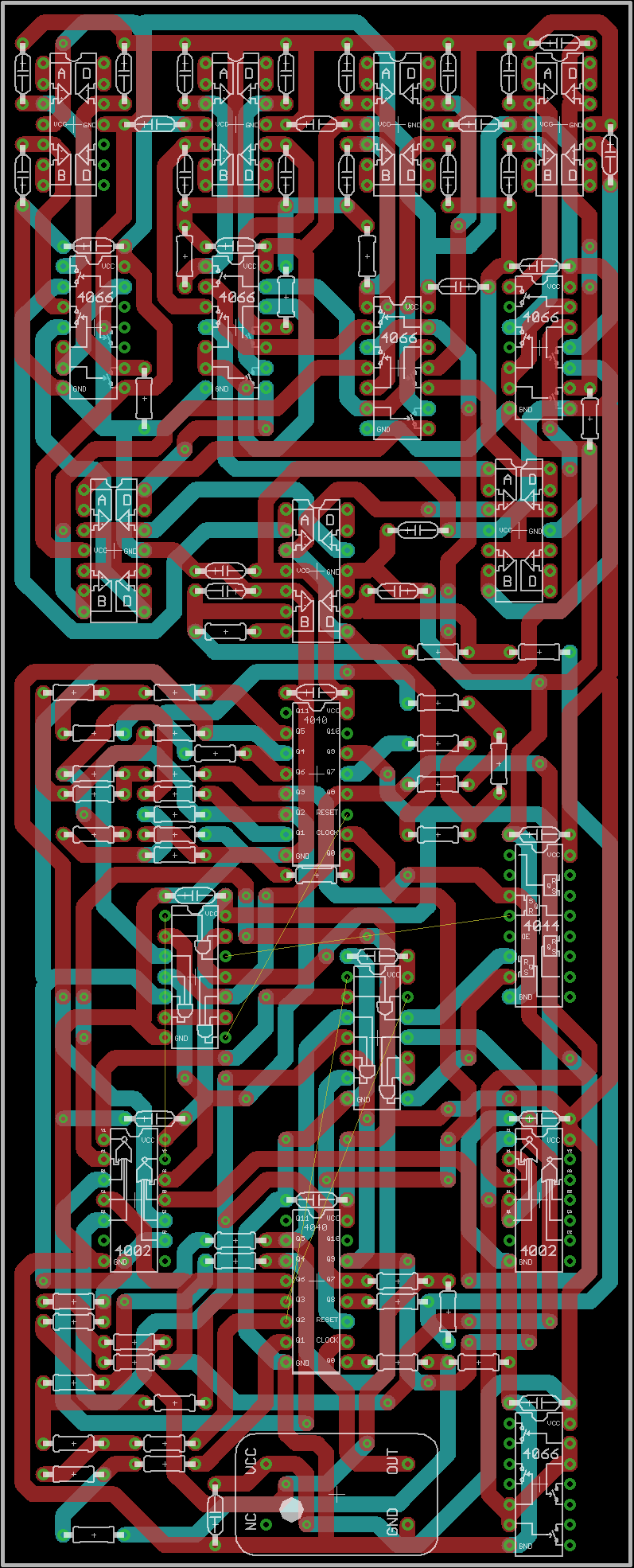
I really didn't like this board. My goal was to design all circuit boards such that they could be constructed on regular perfboard (100mil grid). This meant I needed a lot of space for the spaghetti of traces required to connect all the logic gate chips . I had to make it a double sided board with diagonal traces just to get everything hooked up (not easy to replicate on a perfboard). Even with the double layers there were still several jumper wires required.
Discussions
Become a Hackaday.io Member
Create an account to leave a comment. Already have an account? Log In.