 Russell Kramer
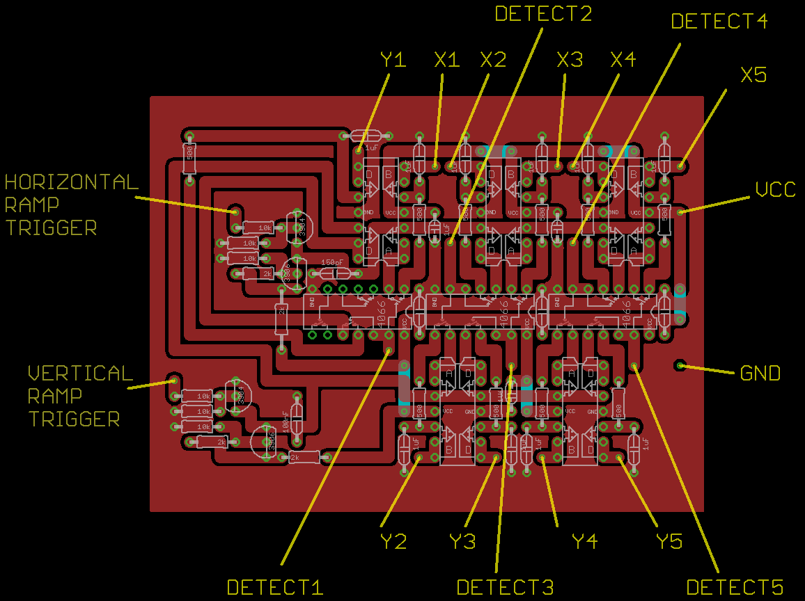
This is very similar to the circuit design used in the NES Zapper project except now there's five separate X,Y sample-and-hold pairs sharing a common pair of horizontal and vertical ramps. I've improved the design by adding a resistor in series with each holding capacitor. This prevents the voltage it holds from changing values too quickly which keeps the X,Y outputs from being jittery. This makes video effects driven by the X,Y outputs look a lot better.
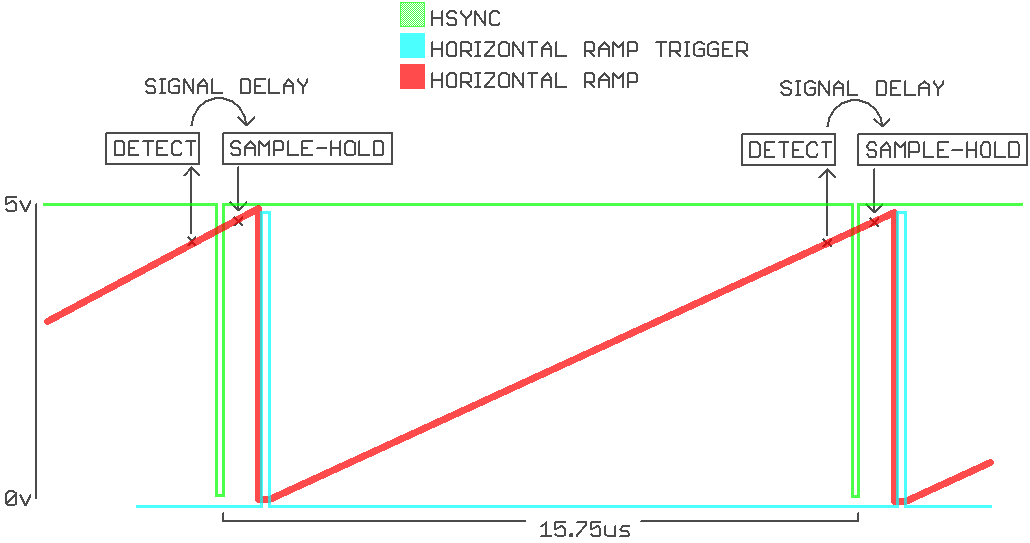
The ramp generators have one less transistor in them now. Last time I was using Hsync and Vsync as ramp triggers and those are normally high pulse low. The new VGA board outputs a separate set of ramp trigger pulses that are normally low and pulse high so there's no need for a transistor NOT gate between them and the ramp circuits.
One less transistors is a nice bonus, but the primary reason for not triggering the horizontal ramp with the Hsync pulse is related to signal delay in the light gun. There is a delay lasting about 3 µs between the phototransistor picking up the raster beam and the sample-and-hold circuit recording the ramping voltage. This isn't much of an issue most of the time, the holding voltage just ends up slightly higher than the ramp voltage at the time of raster detection.
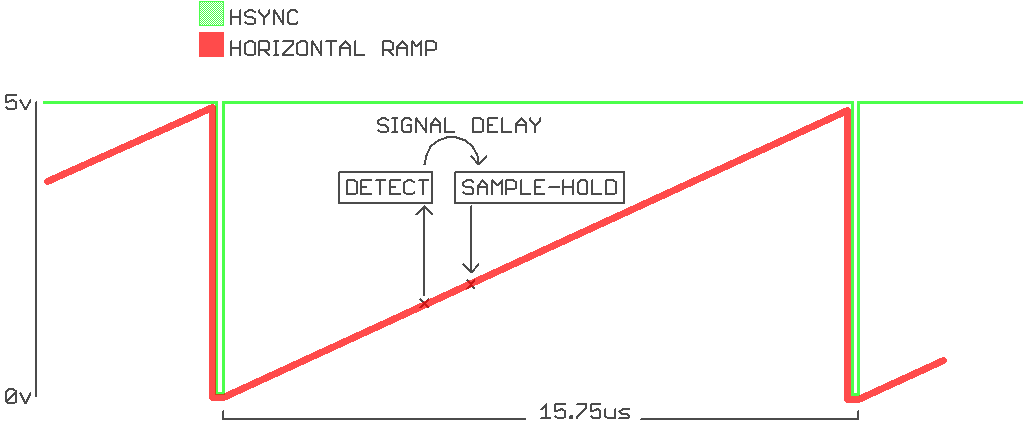
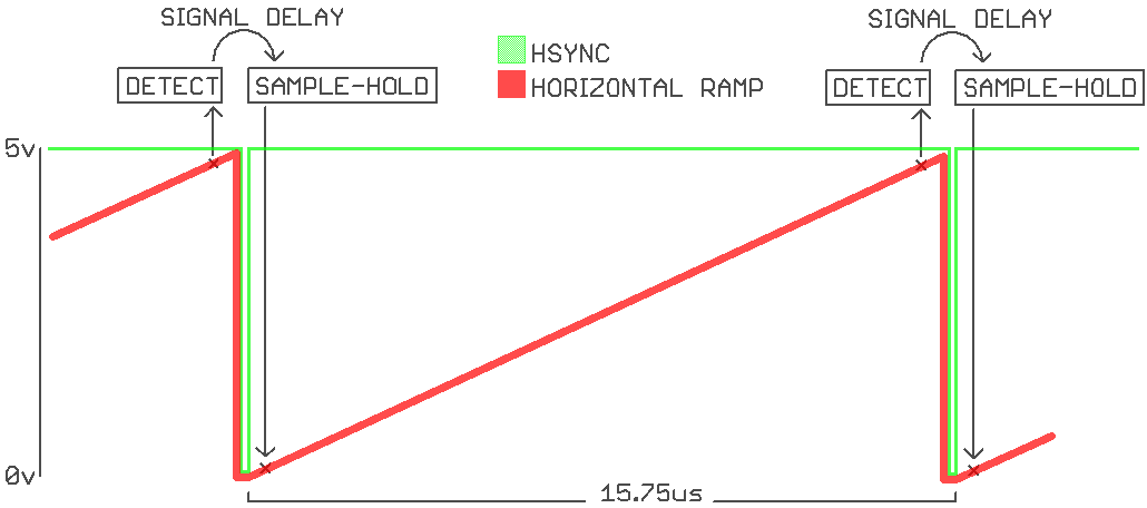
The problem becomes much more serious when the phototransistor is near the right edge of the screen. The ramp circuit is triggered (resets to 0v) between the light detection and the sample-and-hold. This produces a holding voltage that indicates the phototransistor is all the way on the left side of the screen.
The solution was to trigger the ramp circuit slightly after the Hsync pulse. This way when the phototransistor is at the far right of the screen the ramp still hasn't reset by the time the sample-and-hold takes place. I haven't just moved the problem to a different position of the monitor. The detection delay can't overlap the ramp reset because the raster beam goes off (porching) during the period where phototransistor detection would need to take place to cause the problem.
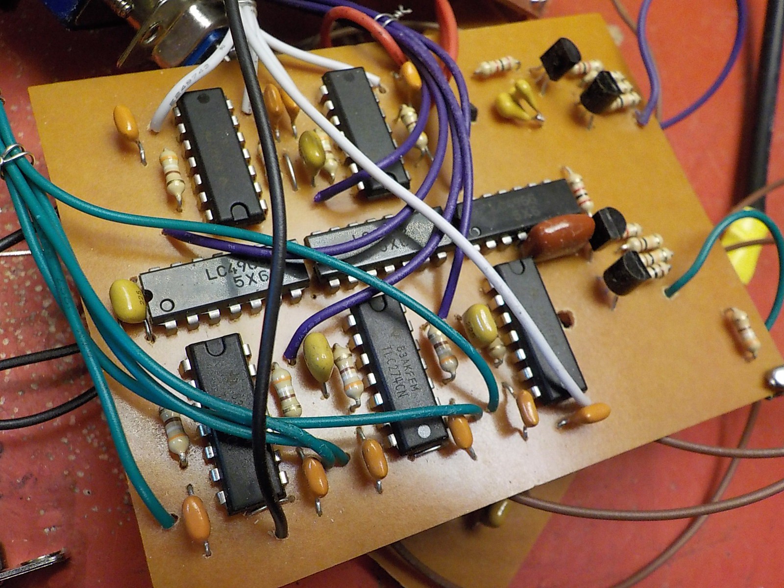
All op-amps are TLC274. Do not use audio op-amps.

The PCB is designed to have the same dimensions as the VGA signal generator board.

Discussions
Become a Hackaday.io Member
Create an account to leave a comment. Already have an account? Log In.