 cb22
cb22Flying wings are tricky things - as I've learnt the hard way, the CG is extremely important, much more so than on a normal plane. (Compare with incorrect CG vs properly adjusted). This can quite limit your options in terms of component placement. In a pusher design, you'll need heavy batteries up front to bring the CG to the correct location.
A flying wing can be characterized by 4 basic parameters, the wing span, root chord, tip chord and sweep. There's a handy calculator online that will generate a wing as well as calculate the optimal CG location based on these parameters.
The next step was to choose these parameters to maximize both capacity and flight time. I'm certainly not an aeronautical engineer, but going from online reading, as well as other videos on YouTube, you can figure out how these parameters affect the overall performance of the wing.
Eventually, I thumb sucked some design parameters (deep-link to the calculator):
| Wing span | 1520mm |
| Sweep Angle | 25 degrees |
| Root Chord | 400mm |
| Tip Chord | 200mm |
| Airfoil | KFm2 |
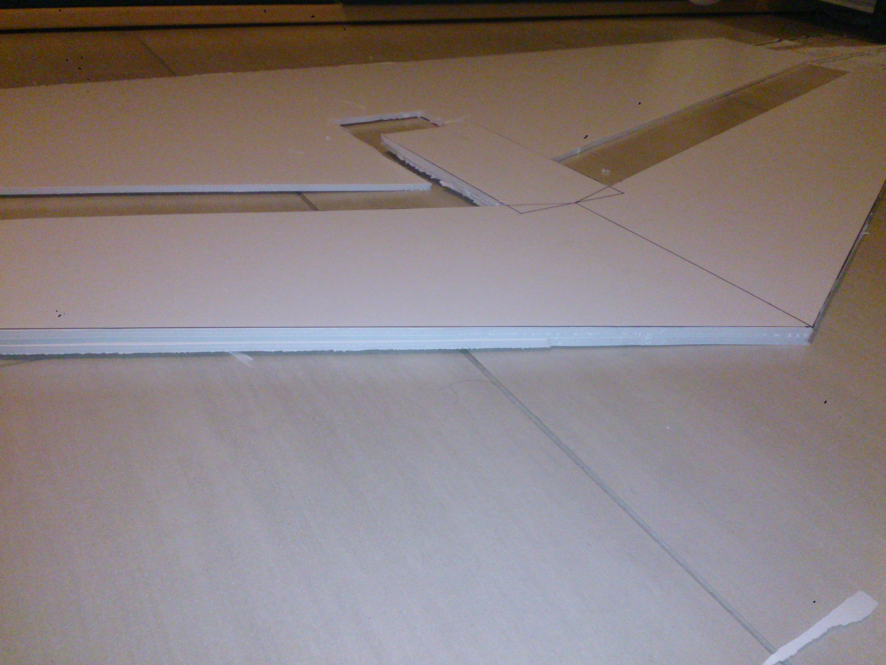
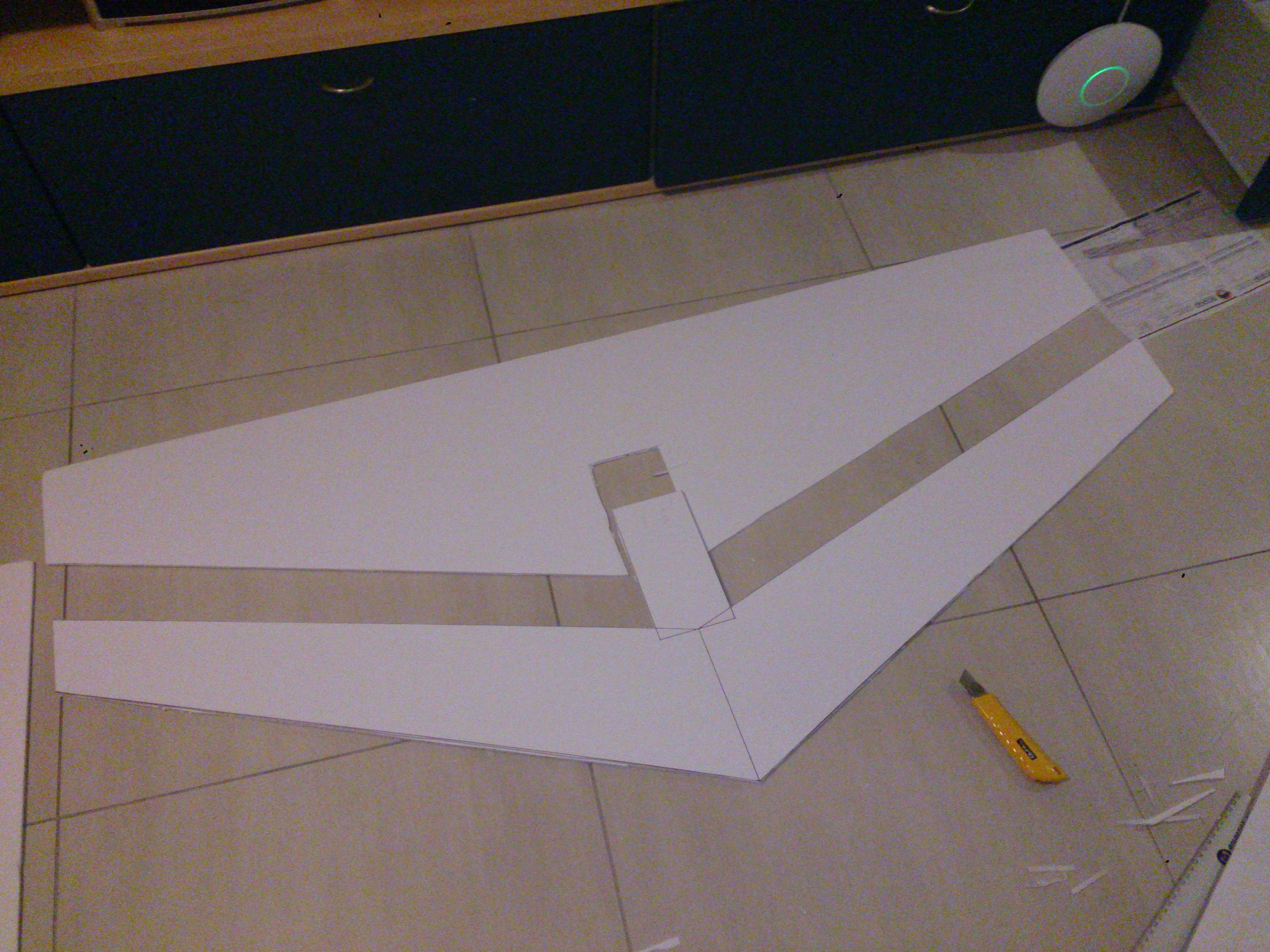
The wing span was chosen simply because that's the largest size of foam I can easily obtain, and the root chord and tip chord were chosen to be in a 2 : 1 ratio. The "airfoil" will be a KFm2, which is extremely easy to build, and apparently gives decent performance. Essentially it is just a stepped airfoil, with a single step on the top at 50% of the chord.
Both the FPV49v2, from FPVTrond and the Raptor 140, by MyGeekShow served as the primary inspiration. This design will have the same airfoil and motor mounting style as the FPV, while keeping the elevon style from the Raptor.
So far I've cut out the upper half of the KFm2 step. Hopefully I'll be able to finish assembling this soon and test it out, then get some proper build instructions up - as well as few videos of me crashing it into the ground :)
Discussions
Become a Hackaday.io Member
Create an account to leave a comment. Already have an account? Log In.